Many of our customers desire the ability to transform Civil 3D data between coordinate systems. This was challenging or impossible…until now! Read on…
It is available for Civil 3D 2019-2022. Read more about this extension here.
The Autodesk® PPK Survey Extension 2022 for Civil 3D® provides an interface for importing GPS data (in RINEX format) for analysis, reporting, and converting it to coordinate geometry points in an Autodesk Civil 3D drawing. Once installed, users can access the Autodesk PPK Survey Extension 2022 for Civil 3D commands via the Autodesk Civil 3D Toolbox.
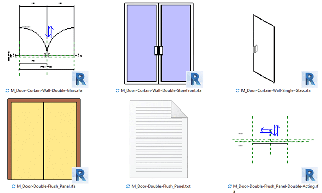
When you are looking at inserting a family, you will want to get the most amount of information about the family file in the shortest amount of time. Without tools like HIVE you are limited to 2 sources of information, the name of the family and the preview image.
Figure 1. Multiple preview directions in the Door Family Folder on my computer
You can control the family naming convention for your company, so why not do the same with the preview image.
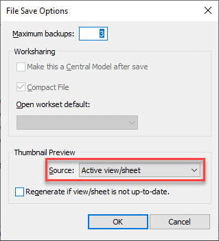
Do you know how the preview image for a Revit family is defined? Its very simple, it’s defined in the File Save Options for the family:
Figure 2. Setting the thumbnail manually
The default in the Generic Model Template is that the Active view/sheet is used for the Thumbnail. This means that anytime you save the file you need to make sure that the view is setup for the presentation you want to see, this takes time and if most often overlooked.
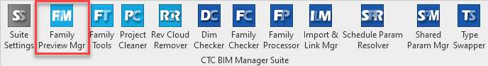
The Family Preview Manager from CTC enables you to control the preview image for multiple files:
Figure 3. Free tools have the lighter tool image
It is also one of the Free tools within the CTC BIM Manager Suite.
Settings for the tool are found within the Options.
There are general settings for things like whether to create backup files as well as which item should be hidden, for example, text and reference planes.
Then there are Appearance settings and here you can select the View direction, Style, Detail level and more. So here you can define that it will be in the Realistic graphic style from the 3D Left Front Top view with the Fine Detail level. You can define the Default Appearance which will be for any categories that do not have an Appearance Template defined.
Appearance Templates are then used for any catalogs that will not use the Default Appearance, for example Tag categories would be best saved in a Plan View rather than a 3D Isometric view.To use an appearance template, setup the template then assign categories to it. Note that you can assign templates for different hosting methods of families, this is important when you think of the orientation of content when face or wall based.
You can select between the Active Family Document or multiple family files with the Document Batch option, however, Active Family Document will of course require that you have a family as the current open file.
Once you have selected the files to be processed you will have the option to overwrite the family or save to a new location, I recommend using the save to new location when you are testing the tool, once you are comfortable with the results then use the Overwrite Family option.
The end result of this tool? Consistency in your family library, all with a free tool from CTC, here is the link to download the tool:
Earthworks Processor is a great tool in the CTC CIM Project suite for automating hours of surface creation and manipulation for the purpose of calculating dynamic and accurate earthworks quantities. With the use of a finished grade surface, existing grade surface, and simple closed polyline “regions”, Earthworks Processor will create 6 different surfaces including a stripping surface, earthworks volumes surface, and a subgrade surface. As well as offer bound volume outputs in the form of tables and labels.
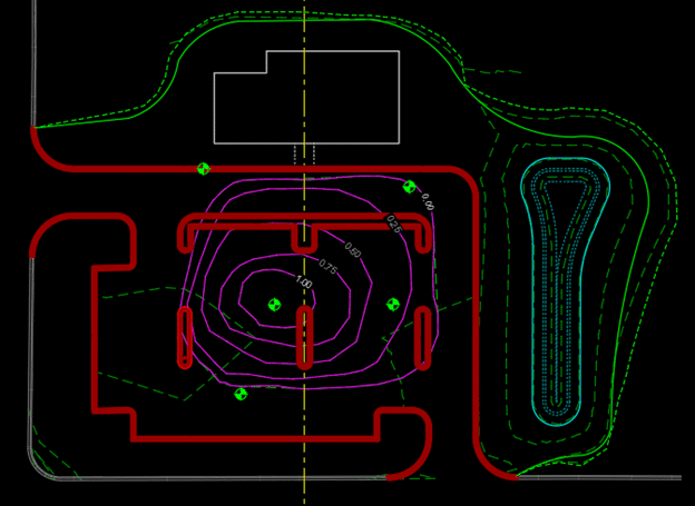
Today I want to talk about an alternative use for EWP. A dynamic way to calculate volumes and map profiles of points of interest from borehole data. This data could be anything from tops or bottoms of contaminant plumes to bedrock mapping, to volumes of loam that cannot be used for backfill. Borehole data of such points of interest is generally represented in depths from the existing surface, not elevations, and it can be tedious to get correct elevations mapped out.
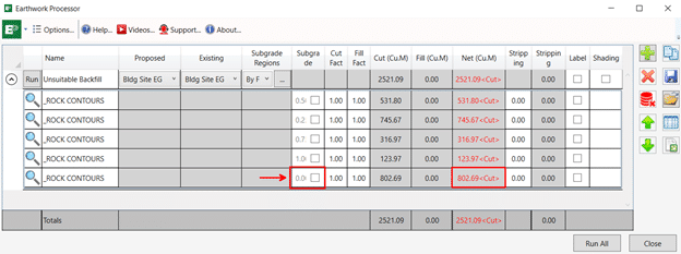
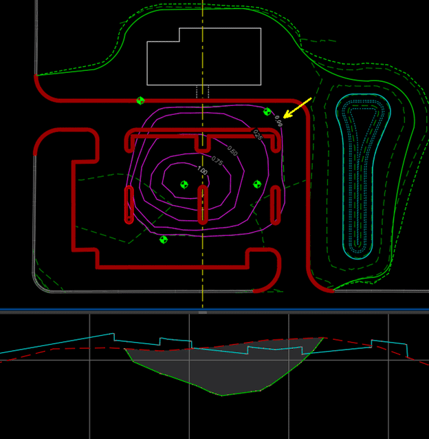
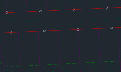
EWP only requires the existing surface and some closed regions identifying depths of the unsuitable backfill (in this case). I have mapped this out as depth contours in the capture below.
These depth contours are derived from the borehole data, but without manually calculating, there is no efficient way to turn these depths into true elevations.
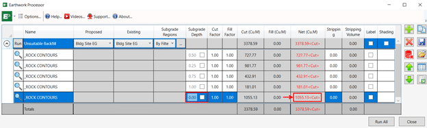
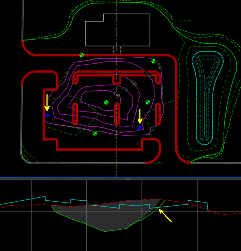
EWP can take these depths and run them through its processing to produce surfaces relative to the varying elevations of the existing surface as well as get you accurate volumes that will be dynamically updated as new borehole information is added to the design. In this scenario it’s the polyline region with the depth of 0 (or the extents of the unsuitable fill) that will give us the volume of unsuitable fill that we are looking for.
This whole process from mapped estimated depth contour polylines to dynamic volumes and surfaces is about 5 mins. The power and ROI of EWP is even more apparent when additional borehole information is added. Depth contours are modified, and EWP is rerun, and surfaces and volumes are updated in seconds.
I would like to acknowledge Jae Kwon, another Civil Technical Consultant on our SolidCAD team for this alternative EWP workflow. I hope this blog post earned your time today and helps you save time on future projects as well.
We are pleased to announce that our partner CTC Software released Civil 3D CIM Project Suite, version 22.0.3. It is now released and can be accessed on the CTC website.
Below are release notes:
22.0.3
9/17/2021
CIM Project Suite
Auto Grader
Bug Fix
Fixed an issue where “split points” in parent feature lines were causing an error. Fixed an issue where creating parallel child lines with a specified station range caused unexpected results. Fixed an issue where inward and outward offsetting was giving unexpected results. Fixed an issue where perpendicular child feature lines were not creating at the user-defined station values. Misc. user interface improvements.
22.0.3
9/17/2021
CIM Project Suite
Corridor Mapper
Bug Fix
Fixed an issue where corridors with disabled regions were causing the app to fail. Fixed an issue in how the app dealt with corridors containing previously mapped targets.
22.0.3
9/17/2021
CIM Project Suite
Corridor Splitter
New Features
Added interactive region selection and graphical highlighting, providing a much more intuitive app workflow.
22.0.3
9/17/2021
CIM Project Suite
Earthwork Processor
Bug Fix
Fixed an issue where the region offset command would not work on very small region objects.
22.0.3
9/17/2021
CIM Project Suite
Label Genie
Bug Fix
Fixed an issue where pipe networks could no longer be labelled.
22.0.3
9/17/2021
CIM Project Suite
Pipe Planner
Bug Fix
Fixed an issue where part elevations were not updating in the app after applying changes to the drawing. Fixed an issue where part elevations were not updating when importing external spreadsheets. Fixed an issue where pipe lengths for the pipe depth at interval property were not calculating correctly. Fixed an issue where parts of the same name, but in different pipe networks, were not allowed by the app. Fixed an issue where the structure rotation angle was incorrectly rounding.
Label Genie can save you a ton of time by creating all sorts of useful labels quickly. Here’s 15 examples that you can use right now.
Descriptions of the settings are included, but to really get up and running quickly Label Genie template files and the sample DWGs have been made available as well. Simply copy the .lg files into %AppData%\CTC\Label Genie then open up Label Genie. They will then show up in the dropdown box in the Label Genie template section.
If the labels you are creating are for design purposes, you may want to set their layers to a non-plotting style that you can ignore, or a layer that you can just freeze without affecting others.
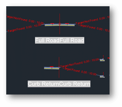
Labelling for Corridor Design (*Corridor Design.dwg)
1. Label Assemblies (*Assembly Name.lg)
Make it easier to which assembly is which at a glance by label their names. The labelling is done with a field, so that if the assembly name changes, a simple regen will update the label.
Type = Multiline Text
Anchor Object = Assemblies (Layer filter = *)
Formatting, contents = (Assemblies).(Name)
Formatting, Y offset = -4
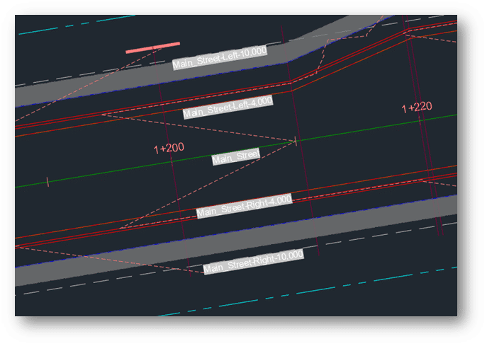
2. Label Alignment Names (*Alignment Name.lg)
When doing corridor work, we may want to see alignment names at a glance. This is especially true if setting up a lot of labels with the Corridor Mapper, for instance. Label the alignment names at regular intervals, oriented with the lines to avoid having to check the property palette constantly.
Label Type = Multiline Text
Anchor Object = Alignments (Layer filter = *)
Anchor Point = Vertices (Interval = 100, rest unchecked)
Formatting, contents = (Alignments).(Name)
Formatting, orientation = To Objects
Formatting, Y Offset = -0.5
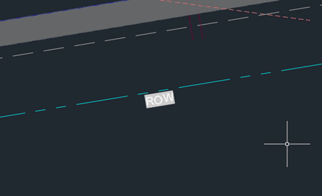
3. Label Feature Line and Polyline Layers (*Feature Line Layer.lg / Polyline Layer.lg)
Continuing the theme of adding some labels to corridor target objects, we can label feature line (and polylines) layer names at intervals. For feature lines, you may want to switch the Contents to the feature line’s name instead of the layer name – depending on how you like to use feature lines.
Label Type = Multiline Text
Anchor Object = Feature Lines (Layer filter = *)
Anchor Point = Vertices (Interval = 100, rest unchecked)
Formatting, contents = (Feature Lines).(Layer)
Formatting, orientation = To Objects
Formatting, Y Offset = -0.5
If you have a lot of polylines for use for horizontal target condition subassemblies, you can label those as well, to make it easier to see what layer names they have. They tend to be shorter, so instead of intervals, midpoints might be more appropriate.
Label Type = Multiline Text
Anchor Object = Feature Lines (Layer filter = *)
Anchor Point = Vertices (Interval = 100, rest unchecked)
Formatting, contents = (Feature Lines).(Layer)
Formatting, orientation = To Objects
Formatting, Y Offset = -0.5
Labelling for Presentation (*Presentation.dwg)
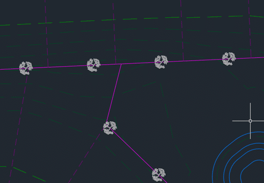
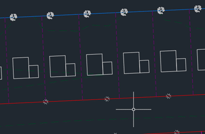
Sometimes, we need to fill in some objects in the drawing for conceptual presentation. At the conceptual stage, we can forego precise placement and mass populate objects such as trees, lights, and structures quickly. These objects, in turn, can be exported to InfraWorks for even greater visual impact.
4. Place Tree Blocks at Back of Lots (*Place Trees.lg)
First, we can place some trees at an interval at the back lot line.
Formatting, rotation / x offset / y offset = 0 / 0 / -8
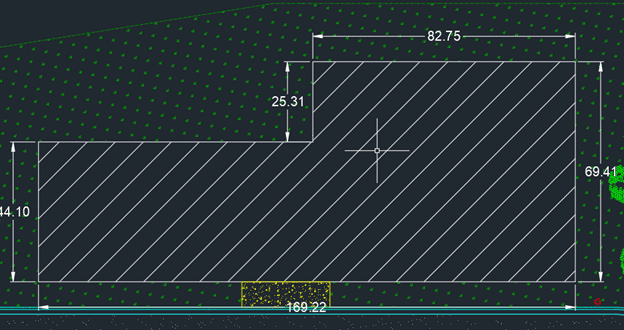
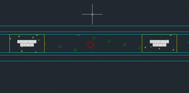
9. Measure Areas (*measure areas.lg)
Next, we generate area quantity labels for various hatching in the drawing. Note that labels are created in the centroids of hatches. This means that if you have an “L” shaped hatch, such as the grass in this drawing, the label may end up being outside the hatch. Some manual repositioning may be required.
Label Type = MultilineText
Anchor Object = Hatches (layer filter = *)
Anchor Point = Centroid
View Type = Plan
Formatting contents =
(Hatches).(Layer)
<New Line>
(Hatches).(Area)
Field customization: Format = Decimal, Precision = 0.0, Suffix = sq. m.
Formatting, Style = Annotative
Formatting, display width = 12
More Labelling Tips On the Way
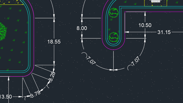
That concludes the first 9 of the 15 time-saving shortcuts using the CTC Label Genie. It can help us quickly generate labels that can help us find the design information we need, place blocks to flesh out a conceptual design drawing, and dimension and measure various objects.
Keep an eye out for Part 2, where we cover locating points and objects, as well as communication key surface information.
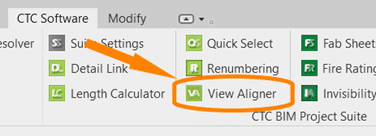
The CTC BIM Project Suite is geared towards users doing the project work, the included tools aim to make everyday project work easier and more efficient that using Revit tools alone. There are 5 free tools accessed from the ribbon while working in Revit, as well as Revit Properties which is access from the File Explorer to allow you access to Revit file properties, such as the Revit version. The paid version of the Project Suite has an additional 13 tools to add to the Revit workflow. The 2022 release of CTC BIM Project Suite saw the addition of a new free tool, View Aligner.
This tool allows you to select any view on a sheet and align the other views to it based on your project needs. The greatest advantage to the View Aligner tool is that it works across sheets.
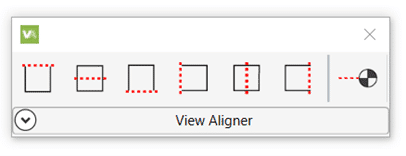
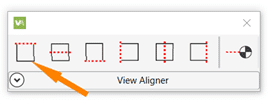
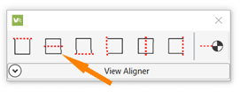
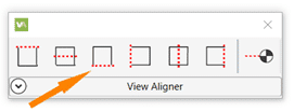
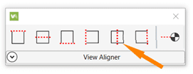
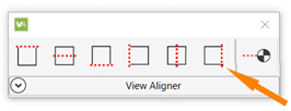
When selected from the tools on the ribbon the floating tool bar appears and can be repositioned to a convenient location.
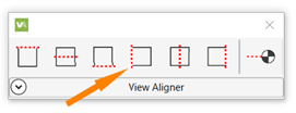
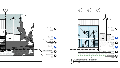
You have the option of 7 alignments, based on the crop boundary of the views. You can align by each edge; top, bottom, left or right, by either horizontal or vertical centerlines, or by levels.
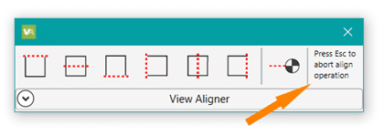
Upon selection of the desired alignment, instructions for ending the operation appear at the end of the toolbar.
If you click back on the toolbar before pressing Esc you will need to click back into the view (so the toolbar goes white again) before you can press Esc to exit.
Align Horizontally by Top Edge
Select the Align Horizontally by Top Edge icon.
Select the view with the position you want to align to.
Every view you click will now align horizontally top edge to top edge of the crop region.
Press Esc to complete the operation.
To keep crop regions the same size for all plan views, use a scope box to control the edges.
Align Horizontally by Centerline
Select the Align Horizontally by Centerline icon.
Select the view with the position you want to align to.
Every view you click will now align horizontally centerline to centerline of the crop region.
Press Esc to complete the operation.
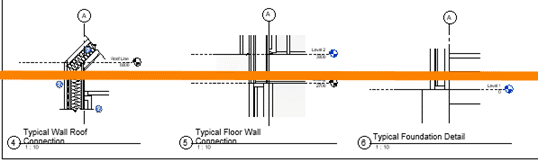
For details that don’t show the crop region try using centerlines to get the massing relatively aligned then adjust view names for a nice symmetrical look.
Align Horizontally by Bottom Edge
Select the Align Horizontally by Bottom Edge icon.
Select the view with the position you want to align to.
Every view you click will now align horizontally bottom edge to bottom edge of the crop region.
Press Esc to complete the operation.
Align the bottom of images to help determine the spacing for other elements on the sheet.
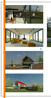
Align Vertically by Left Edge
Select the Align Vertically by Left Edge icon.
Select the view with the position you want to align to.
Every view you click will now align Vertically left edge to left edge of the crop region.
Press Esc to complete the operation.
Align images along the edge of a page for a nice crisp line.
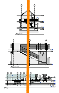
Align Vertically by Centerline
Select the Align Vertically by Centerline icon.
Select the view with the position you want to align to.
Every view you click will now align vertically centerline to centerline of the crop region.
Press Esc to complete the operation.
Vertical alignment by centerline works best with the unrelated views that Revit can’t snap alignment to.
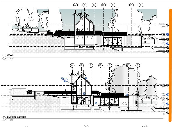
Align Vertically by Right Edge
Select the Align Vertically by Right Edge icon.
Select the view with the position you want to align to.
Every view you click will now align Vertically right edge to right edge of the crop region.
Press Esc to complete the operation.
Using a right edge alignment (or left) for elevations results in a cohesive look when grid bulbs for all views are aligned to the same side.
Align By Levels
Select the Align by Levels icon.
Select the view with the position you want to align to.
Every view you click will now align by levels.
Press Esc to complete the operation.
To use this alignment the scale of the views must be the same.
TIPS:
Use the View Alignment tool to align ‘like’ items.
Assign a scope box to the crop regions to make alignment quicker.
Open each sheet you will be working on before starting the tool to use alignment across the sheets. You cannot access the project browser once the tool is active. Use the view tabs to flip between sheets to align the views horizontal across each sheet, then do the same to align vertically.
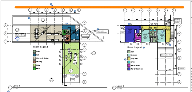
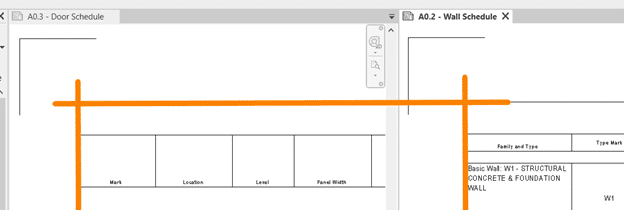
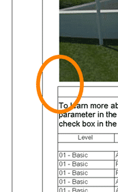
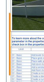
Alignment works best on views of the same type. As seen below when you align an image and a schedule the space between visible content and the outermost edge of the crop boundary are not the same so despite being aligned the appear “off”.
Get your 2022 release of CTC BIM Project Suite and try the FREE View Aligner tool on your next project. Reach out to us at info@solidcad.ca
We are excited to announce that our partner CTC Software released Civil 3D CIM Project and Manager Suites, version 22.0.1. It is now released and can be accessed on the CTC website.
This update saw a lot of fixes and enhancements to new products released in 22.0.0 and before.
Below are release notes:
22.0.1
8/17/2021
CIM Project Suite
Pipe Planner
Bug Fix
Fixed a variety of issues causing Pipe Planner to error out or crash. Improved application speed performance. Fixed issues with exporting to external spreadsheets. Fixed issues with importing external spreadsheets.
22.0.1
8/17/2021
CIM Project Suite
Pipe Planner
Enhancement
Added support for formulas in user-defined empty columns and rows. Added properties filter search bar. Added interactive selection of export starting cell. Improved part renaming, allowing old names to be reused on new part names within the same operation. Added new right-click options to edit the middle table. Misc. enhancements and performance improvements.
22.0.1
8/17/2021
CIM Project Suite
Pipe Designer
Enhancement
Improved part renaming, allowing old names to be reused on new part names within the same operation.
22.0.1
8/17/2021
CIM Project Suite
Label Genie
Enhancement
Added option to manually select anchor objects in drawings. Added option when labeling layouts to create a unique layer for each layout.
22.0.1
8/17/2021
CIM Project Suite
Label Genie
Bug Fix
Fixed an issue where layout-specific labeling was not respecting exact viewport extents. Fixed an issue where segment labels were not following the assigned layer. Fixed misc. issues with specific drawing files.
22.0.1
8/17/2021
CIM Project Suite
Earthwork Processer
Bug Fix
Fixed an issue where errors occurred if existing or proposed surfaces were empty or not overlapping one another. Fixed an issue where earthwork region polylines that were significantly small would not offset and cause the app to error.
22.0.1
8/17/2021
CIM Project Suite
Data Wizard
Bug Fix
Fixed an issue where survey figures caused Data Wizard to error.
22.0.1
8/17/2021
CIM Project Suite
Parts Swapper
Bug Fix
Fixed an issue where parts not found in the parts catalog were causing Parts Swapper to file.
22.0.1
8/17/2021
CIM Project Suite
Corridor Mapper
Bug Fix
Fixed an issue where changes to assemblies would cause the app to error.
22.0.1
8/17/2021
CIM Project Suite
CIM Project Suite
Bug Fix
Fixed an issue where custom subassemblies were breaking when CIM Project Suite was installed.
22.0.1
8/17/2021
CIM Manager Suite
Template Tracker
Bug Fix
Fixed an issue where pressure network band styles were causing Template Tracker to error out.
22.0.1
8/17/2021
CIM Manager Suite
CIM Manager Suite
Bug Fix
Fixed an issue where custom subassemblies were breaking when CIM Manager Suite was installed.
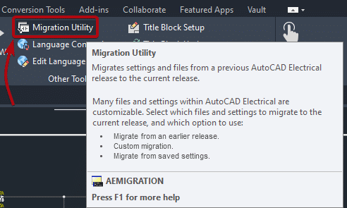
Every year Autodesk releases a new version of the software which often contains new features, bug fixes and overall improved stability, so a common question that we get from our customer is: how do I move all my custom settings, symbols, databases, etc. to the new version of AutoCAD Electrical. Included with AutoCAD Electrical is the “Migration Utility” which allows the user to move all your customized settings, custom libraries (symbols + icon menus), databases, etc. This utility can be found inside the “Project” tab as displayed on Figure 1.
Figure 1
In this blog article we will cover the steps requires for us to upgrade and migrate from one version to another. Once we have downloaded and installed the new version of AutoCAD Electrical, we close all other Autodesk software that so we can start the “Migration Utility”.
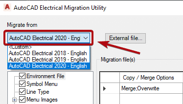
Figure 2
In this configuration window we are required to select the previous version that we want to migrate from. Clicking on the dropdown arrow will display all the previous versions installed on the local machine. If you have more than one version installed, you need to select the software version that has all the latest customization/libraries of the software as seen on Figure 2.
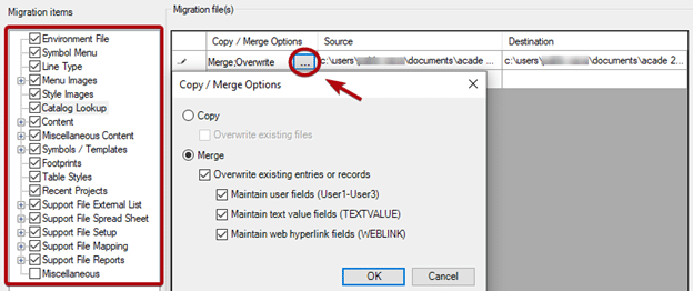
After we select the version that we want to migrate from, the next step is to select the items we want to migrate. Those items can be found under “Migration items” and, by default, all of them are going to be selected as seen on Figure 3. If we click on any of the individual items, we will find the option to copy or merge the pre-existing information. Keep in mind that each migration item might have a different preset value here so make sure you review all the items that need to be migrated.
Figure 3
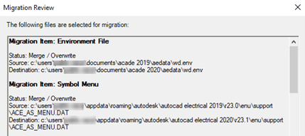
Once we have reviewed all the migration items we need to click “OK” so the migration process can start.
Figure 4
Before the migration gets started, a “Migration Review” window is going to popup with a summary of all the files that are about to be migrated as seen on Figure 4.
After a final review we are ready to click “OK” so the migration process can start.
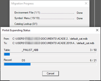
While the migration is in progress, a window is going to popup showing the file currently being migrated and the current progress status as seen on Figure 5. Keep in mind that depending on the size of your customized files (databases, etc.), this process could take from minutes to several hours.
Figure 5
When the Migration is complete a summary window similar to the migration review will popup specifying, once again, all the files that were migrated.
The last step is to restart the software so you will be ready to use your new version of AutoCAD Electrical without losing any preexisting customized files/settings.
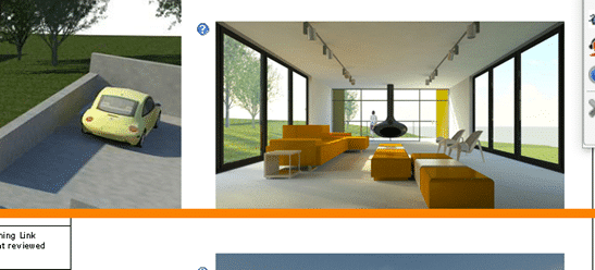
With Lumion, you can render more than a building. Render your client’s dream home, render a story about design that moves emotions, render the space where life happens.
A building begins as a structure. Walls. Floors. Roofs. Windows and doors. All expertly crafted into a beautiful arrangement of form and function.
When looking at the 3D model, however, you might feel as if something is missing. Maybe it doesn’t capture the energy and atmosphere of the space and its surroundings. Perhaps it doesn’t ignite emotions or make you want to be there. Whatever it is, there’s something about life that’s just not easy to show in CAD.
With Lumion, you can bring your vision to life and tell a richer, more immersive story about the design’s role in the real world. A story that sparks imagination and helps clients fully visualize how life could unfold within those four walls.
From the small experiences you share with others to the objects that decorate your home, life is full of feeling. The sofa, coffee table and chairs in the living room, for instance, become a gravitational center where families share peaceful moments together. Papers and pens and books are scattered across a busy home office desk, alongside used coffee cups and photos of loved ones. In the kitchen, the teapot boils and toast pops out of the toaster, signaling the start of a new day.
These are not just objects, they are reflections of life. They fill spaces with character.
Lumion helps architects unveil their designs as lived-in spaces, capturing the deeply personal connection between a building, the people who inhabit it, and all the unique objects they bring with them.
You can render more than a building. Render your client’s dream home, render a story about design that moves emotions, render the space where life happens.
What’s new in Lumion 11.5
The latest version of Lumion reinforces its ability to make spaces feel alive with the everyday activities that occur there. You can let your imagination loose and tell a story about a room, a building, or even the entire project, exactly as you see it in your mind’s eye.
Lumion 11.5 Pro comes with 123 new objects* in the content library, making it easier to add a human, personal touch to your renders. You can find 73 new retro-inspired objects that reveal the unique identity of spaces, including:
36 eye-catching kitchen objects, including blenders, refrigerators, toasters, mixers and more.
12 furnishings from another era, including café tables and chairs, a jukebox, a popcorn maker and more.
11 timeless pieces of office furniture, including sofas, desks, chairs, table lamps and more.
14 other stylish items, including clocks, radios, a sewing machine, TVs and more.
Additionally, you can express delight throughout your scene with 50 new 3D characters, including a diverse variety of children, teens and adults of different backgrounds and cultures.
These cheerful non-animated characters are ideal for communicating context, scale and emotion in the background of your project, whether it’s a sunbather relaxing on the grass, a child looking up with wonder, or a couple enjoying a beautiful view together.
There are infinite stories to tell about your design with the mix of new 3D characters and retro-inspired objects in Lumion 11.5. When combined with Lumion’s existing content library of over 6,300 assets* and over 1,250 materials*, you’ll find yourself on a smoothly paved road to rendering creativity, to bring your designs to life.
Availability
Lumion 11.5 is available from June 1st, 2021, as a free update for Lumion 11 and Lumion 11.3 users. Lumion 11 users can download the updated version on your Lumion Account.
We are excited to announce that our partner CTC Software released Civil 3D CIM Suites for version 2022. It is now live and can be found on the CTC website.
The update can be downloaded from the about menus in the apps.
For network licensing you will of course need new license files, which can be requested here: LicenseRequest@ctcsoftware.com.
Standalone licensing has been updated already for current subscriptions.
This release saw support updated to 2019-2022, a major new app for pipe networks, a completely rebuilt app for corridors, and many new features and fixes across the majority of the tools and both suites.
Release notes for CIM suites 22.0.0:
Version
Date
Suite
Component
Type
Detail
22.0.0
6/24/2021
CIM Project Suite
Pipe Planner
First Release
Load pipe networks in an in-app spreadsheet or export to external spreadsheets. Edit parameters and perform analyses in the spreadsheet then push changes back to the pipe network. Create customized manhole schedules, pipe depth reports, and detailed QTO.
22.0.0
6/24/2021
CIM Project Suite
Corridor Mapper
New Features
Completely rebuilt the legacy Corridor Mapper tool to a new app. Corridor Mapper version 2 allows for linking of subassemblies to styles and object names. Can also now select multiple subassemblies at once an assign targets to all of them. Subassemblies can now be mirrored to other subassemblies, so that when the source one changes all the dependent subassemblies update with it. A default surface can be assigned for surface targeting so that as new surface type subassemblies are added to the corridor their surface target will automatically assign. Users can filter out objects by type. Manual selection of targets has been added. A list of current targets is now available to view targets assign automatically and manually to a given subassembly.
22.0.0
6/24/2021
CIM Project Suite
Auto Grader
Bug Fix
Fixed an issue where loading certain grading family templates caused an error. Fixed an issue where parent features lines being added to a surface in template insertion family types were causing odd surface behavior. Fixed an issue where naming a child grading component “parent” would cause the app to crash. Fixed an issue with template grading families where deletion of template feature line and subsequent running of a family referencing that template would result in deletion of all child feature lines.
22.0.0
6/24/2021
CIM Project Suite
Auto Grader
Enhancement
Added support for partial station ranges to wrap around the end of closed parent feature lines. Added option to duplicate “split” points in parent features lines as PVIs in child feature lines. Added option in child feature line formatting when grading existing feature lines to “keep source” of existing feature lines. Added option in stations settings where users can specify the starting station to increment from, opposed to it always being 0+00.
22.0.0
6/24/2021
CIM Project Suite
Auto Grader
New Feature
Added new feature for template insertion grading families, where Distance at Slope and Distance to relative Elevation methods can have the template insertion elevation determined by adjacent feature lines, and not just the parent feature line. This allows for smarter placement of grading pads relative to surrounding lot elevations.
22.0.0
6/24/2021
CIM Project Suite
Pipe Designer
Bug Fix
Fixed an issue where using cancel to escape out of the app would not allow a network license to be returned.
22.0.0
6/24/2021
CIM Project Suite
Parts Tagger
Bug Fix
Fixed an issue where using cancel to escape out of the app would not allow a network license to be returned.
22.0.0
6/24/2021
CIM Project Suite
Data Wizard
Bug Fix
Fixed an issue where when object counts were zero the app would error when trying to create a table. Fixed an issue with embedded grids where scrolling didn’t work correctly.
22.0.0
6/24/2021
CIM Project Suite
Earthwork Processer
Bug Fix
Fixed an issue where surface styling defaults in Options would uncheck “match default” when rebuilding earthwork sets. Fixed misc. issues where app settings were not saving correctly for future sessions within the app. Fixed an issue where the app errored on incorrectly drawn polylines.
22.0.0
6/24/2021
CIM Project Suite
Earthwork Processer
Enhancement
Added option to multi-select region rows for mass editing. Added zoom in drawing buttons for each region. Improved the region row visibility when earthwork sets are expanded. Improved messaging when illegal subgrade boundaries are utilized. Improved label placement to use largest area placement instead of centroid. User edits to labels will now not be overridden when earthwork sets are run, including label placement.
22.0.0
6/24/2021
CIM Project Suite
Earthwork Processer
New Feature
New supporting function to all creation of automatic offsets of user-created polylines or feature lines. Users can reference existing region objects by manual selection or filtering and specify an offset distance to quickly create subgrade regions that do not overlap.
22.0.0
6/24/2021
CIM Project Suite
Label Genie
Bug Fix
Fixed an issue where auto-feature lines could not be selected in the drawing. Fixed an issue where erroring occurred when trying to save a template. Fixed an issue where app errored when running line and curve labels. Fixed an issue where the Required Object field for surface type labels was not reseting correctly. Fixed an issue where unfound label styles were causing the interface to glitch. Fixed an issue where child styles for some categories were not appearing in the style lists. Fixed an issue where manual text overrides performed prior to using label genie were being erased.
22.0.0
6/24/2021
CIM Project Suite
Label Genie
Enhancement
Improved user guide explanations for drawing source and label selection behavior.
22.0.0
6/24/2021
CIM Project Suite
Parts Swapper
Bug Fix
Fixed an issue where using retain size option would not properly allow parts to swap if those parts were not found in the parts lists and/or had identical descriptions for multiple part sizes.
22.0.0
6/24/2021
CIM Manager Suite
Layer Boss
Enhancement
Added legend in import results to better understand the different color coding of results. Added column header filters to excel export.
22.0.0
6/24/2021
CIM Manager Suite
Layer Boss
Bug Fix
Fixed an issue where the layers export dialog box wasn’t stretching components correctly. Fixed an issuye where, when the user settings in the user appdata folder did not exist, the app would error out. Fixed an issue where french color spellings were not recognized when export to or syncing from Excel. Fixed an issue where the description column would sometimes be empty when exporting to Excel. Adjust button order on import function to be more industry standard.
22.0.0
6/24/2021
CIM Manager Suite
Layer Boss
New Feature
Add a new column to the excel export titled “New Name”. This will allow users to change layer names in excel, then upon syncing back to the dwg, the layer name will change, but all references to that layer will stay intact.
22.0.0
6/24/2021
CIM Manager Suite
Linetype Manager
Bug Fix
Fixed an issue where certain .shx files could not be read. Fixed an issue where some linetypes would not import. Added support for include periods (.) in the linetype name.
22.0.0
6/24/2021
CIM Manager Suite
Survey Template Manager
Bug Fix
Fixed an issue where block references in point styles were not updated when exporting to Excel. Fixed an issue where multiple description key sets were appearing in the app, but did not exist in the drawing.
22.0.0
6/24/2021
CIM Manager Suite
Template Tracker
Bug Fix
Fixed many issues where certain mleaders, layers, text styles and dimension style references were not found in the drawing. Fixed an issue where sorting by layer in layer editing dialog box caused an error. Fixed an issue where certain drawings would cause a looping error when opening Template Tracker. Added support for Pressure Network related references can now be tracked (2022 version only).