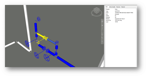
When working on any design, it’s helpful to have data readily available. Typically, when we need to see certain properties of an object in AutoCAD, we would have to select the item and open its properties window.
If you are familiar with AutoCAD, you may know that there is a “Roll Over Tooltip” feature. This lets you hover your curser over an object and see certain information related to it. By default, the information we see is basic. Such as layer, color, and line type.
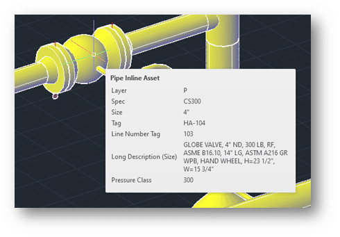
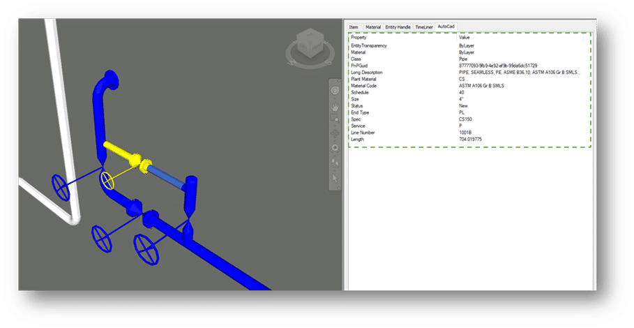
Did you know that Plant 3D utilises this feature as well? As you can see below, hovering over a valve brings up specific Plant 3D information. This is very helpful when we need to require information quickly.
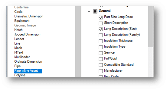
But what if the information displayed is not enough? By going into the AutoCAD CUI settings, we can toggle additional fields for the tool tip. In this example, I have turned on Long Description (Size).
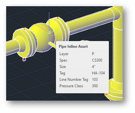
Hovering over the component now displays the Long Description information as well.
The AutoCAD CUI settings has integrated Plant 3D properties with its tool tips feature. It has given us the ability to toggle additional information from your Plant 3D design. Thanks for tuning in and I hope this information is useful.
One of the strengths of AutoCAD Plant 3D is its customizability. For example, it allows users to build custom P&ID symbols and tags to suit their project needs. Whenever I conduct Plant 3D training, I’m always asked if there is a way to copy custom symbols from one project to another. Unfortunately, my answer was always no. That is, until this new feature of AutoCAD Plant 3D 2022.
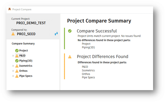
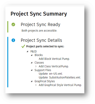
Say hello to Project Compare. Project Compare allows you to see differences from 2 projects and lets you sync data from one to the other.
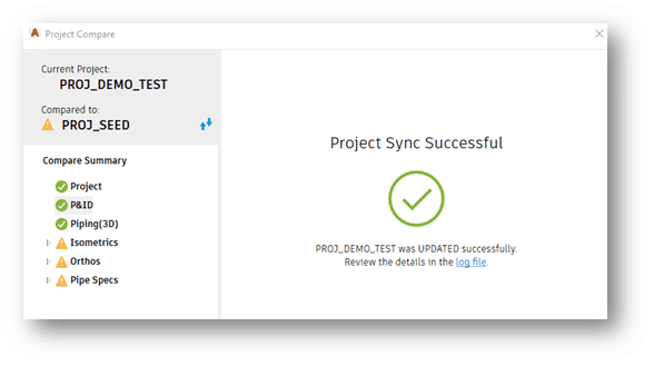
In this example I am comparing a SEED project with a DEMO project. The SEED project contains the custom P&ID symbol. As you can see, the tool compares more than just P&ID objects.
I’ve selected the P&ID category and applied the synchronization settings. The preview will provide a list of what items will be synchronized. After reviewing the information and a few clicks I can now bring in the custom symbol into my DEMO project.
After the synchronization process, the DEMO project is now updated with the custom symbol from the SEED project and is ready for use.
This new feature is time saving. There is no longer the requirement of rebuilding the symbol for new or existing projects. You can just compare and synchronize.
If you would like more information on this process, please don’t hesitate to contact us.
In my previous blog, I explained how Navisworks can complement Plant 3D.
Now I will show you how to enable some Navisworks features directly within Plant 3D, or any AutoCAD based products. With this feature enabled the user can export a Navisworks (NWC) file directly from within AutoCAD. They will also have the option to manage the Navisworks export settings.
For this example, I will be using AutoCAD Plant 3D 2021 and Navisworks Manage 2021. If you do not have access to Navisworks you can download the Navisworks exporters from Autodesk directly.
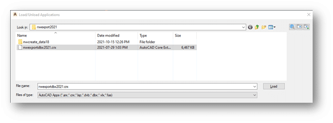
3) Navigate to: C:\ProgramData\Autodesk\ApplicationPlugins\autocad_exporter2021_x64.Addin.bundle\nwexport2021
4) Select crx
5) Click on Load
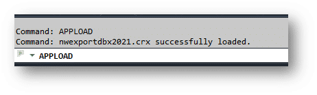
6) It will inform you if the Plug-In was successfully loaded.
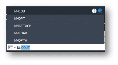
7) To test it, start typing NW in the command line. A new set of Navisworks commands should be available.
8) To export DWG contents, simply type NWCOUT and save the file.
Adding the Navisworks Menu in AutoCAD
With AutoCAD or a DWG open, type CUILOAD in the command line:
1) Click on Browse
2) Navigate to: C:\ProgramData\Autodesk\ApplicationPlugins\autocad_exporter2021_x64.Addin.bundle\nwexport2021\nwcreate_data18
3) Change the File type to “Legacy Menu Files”
4) Select mnu and click open.
5) Click on Load
6) Close the CUI dialog box. If you get a warning message, it is ok to proceed.
If you would like to learn more, Navisworks training is available as a supplementary course to SolidCAD’s Plant 3D course curriculum. Please contact training@solidcad.ca
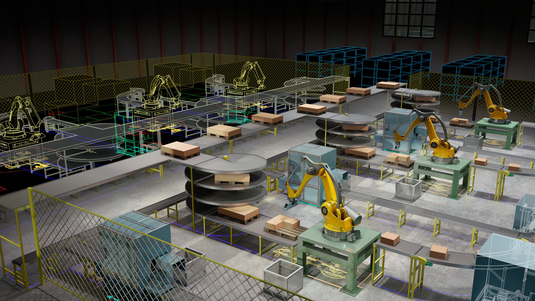
Getting started with product design visualization is easy.
Currently most engineering is accomplished using 3D modeling software’s. It can be done in solids, surfaces, meshes, nurb curves etc. It can be done as freeform, sculpted, parametric design, AI driven even. The possibilities are endless.
Still, somehow, it’s a common misconception in the manufacturing community that product design visualization is a niche discipline and is out of reach. Many companies even think that their products don’t require any type of product rendition because they are not doing consumer products. The fact is, that technologies and 3D models are so common and easily available now a days, that it is assumed by consumers that products are available to view on demands. One would expect to go on a manufacturer’s web site and view catalog products. That goes for any type of products, even heavy-duty industrial machinery. Lacking in product showcases can leave a diminished and negative perception of quality and services by a typical buyer. If people buy with their eye’s, setup a digital photo studio and give them eye candy.
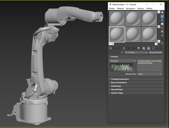
As the title of this blog implies, getting started with product design visualization is easy. In all Autodesk Collection of software’s is included 3DS Max. 3DS Max is an industry standard for 3d modeling, animation, special effects and obviously rendering. It’s comprehensible that at first glance such a software can be intimidating with the thousands of tools and features. Many users opened it just to close it immediately in fright after seeing the user interface. But when it’s come to basic visualization you will only need a hand full of those features. The workflow for a basic Photo studio style visualization is as easy as this:
Import your model
Adjust materials to taste
Set up environment
render
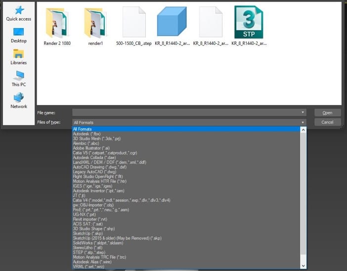
1. Import your model
3DS Max support lots of different file types. The list shown here cover lots of ground and enable easy and efficient importation from any provenance.
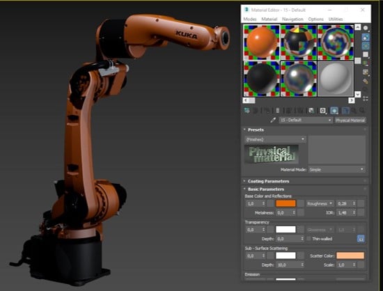
2. Adjust materials to taste
The simplified material editor (Compact mode) is simple to use. I strongly recommend using the physical material since these materials have built in templates for quick creation and those materials are compatible with most renderers.
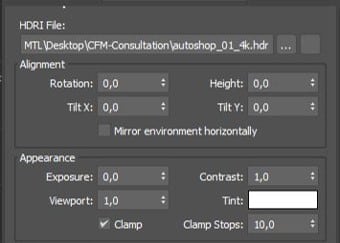
3. Setup Environment
In the environment dialogue box, a high dynamic range image can be imported as the scenes background. Those HDRI images do not only
act as the scene environment but also act as the lighting scheme for the scene. This makes lighting a scene with the desired look a breeze. The high dynamic range image can also be used only as light. The actual environment don’t have to be shown to light the scene so another image can be used as a background. Having real lighting with a backdrop type background creates an excellent studio photoshoot space. 3DS Max come bundled with dozens of High dynamic range images but these images can be easily found by the thousands on the web.
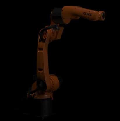
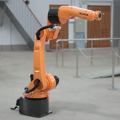
Scene without lightsScene with HDRI environment lightingSame scene with Studio backdrop
4. Render
From there you can render from the viewport as a point and shoot type of work. Cameras can also be created for more control and repeatability. To prove my point, I have done more examples of studio photoshoot style render’s. We can clearly see that this type of rendering is very suitable for manufacturing and industrial products and won’t break the bank.
The learning curve of achieving your first renders with 3DS Max is not steep at all!
Basic software file management, navigation and manipulation are the same as any other software and those knowledges are transposed with no effort. Learning how to set the environment dialogue box, how to use the material editor and how to adjust cameras will require a little work, but not much.
Ask your Sale’s representative at SolidCAD about our new 2 days training; 3DS Max – Photo Studio Rendering.
In a data driven world, information can be the currency that can make or break your project. Misinformation, or the lack of, can cause delays and costly errors in a project’s life cycle.
AutoCAD Plant 3D is a powerful process-piping design tool. Each piping component placed in Plant 3D has useful data embedded in it. This data is crucial for the plant’s overall design. However, this data can only be viewed within the Plant 3D application.
In plant design, data will pass through many hands and in various stages of the project. How do we then share this information to external parties like clients, fabricators or constructors who don’t have the Plant 3D application?
This is where the dependable sidekick comes to the rescue. Navisworks!
Navisworks has the ability to open various file types. It can also read embedded data if the proper object enabler is installed. Fortunately, Autodesk has one specifically for Plant 3D. You can download the 2021 version here.
Here’s an example of a Plant 3D model in Navisworks without an object enabler. You can see that some shapes aren’t displayed properly, and it is not reading the embedded data.
Here is the same Plant 3D model with the object enabler installed. All the components are displayed correctly, and the embedded data is being displayed in the properties section.
With the Plant 3D model in Navisworks, the file can now be saved as an NWD file and delivered to external parties. All they need is Navisworks Freedom to view the file, which can be downloaded for free from Autodesk.
This is one of many features available in Navisworks. Apart from a robust 3D viewer it can perform tasks such as clash detection and animation.
If you would like to learn more, Navisworks training is available as a supplementary course to SolidCAD’s Plant 3D course curriculum. Please contact training@solidcad.ca
In the next blog, we will look at how to utilize the Navisworks plug in within Plant 3D. Stay tuned!
Share a view of your AutoCAD drawing online with others. Those users are not required to have AutoCAD installed since the AutoCAD file is viewed online in their web browser. The DWG is not uploaded to the cloud, only the shared view. Invited participants can view, print, measure, and mark up the view.
Porcupine Engineering is a professional services firm providing clients with a comprehensive range of services including multi-discipline engineering (conceptual and detailed design), project management, planning & scheduling, feasibility studies, cost estimates, procurement, shop inspection & field services, construction management, commissioning and start-up, and production & maintenance support.
With offices in Timmins and Sudbury, Ontario their team is composed of professional engineers, project managers, technologists, technicians, coordinators and support staff.
Project Profile
Challenge
Porcupine Engineering is committed to providing their clients with the highest quality and up-to-date field services and support.
Porcupine Engineering turned to SolidCAD in need of a full-service package that would integrate all software solutions they invested in as well as provide customized training and on-going support for all its staff members. Their goal was to incorporate an improved design strategy that would ensure value and efficiency to their clients and their projects.
The firm began with the purchase of Autodesk software solutions, such as: AutoCAD Plant 3D, AutoCAD P&ID, Revit Structure and Inventor. Prior to their switch, they realized an increase in the use of 3D modeling and client expectation to have projects delivered as a 3D model.
Originally, Porcupine Engineering produced many of their designs as a 2D model, which would often be misinterpreted by their clients— often causing rework, overall effecting the efficiency of their services.
Solution
In order to reduce mistakes and eliminate rework, implementing a comprehensive range of services that are both cutting edge and up-to-date with the changes that are happening within the industry become a priority.
SolidCAD initially provided a presentation and discussion to uncover the existing workflow, than create and deliver a complete customized training package that would include all their technological investment in; AutoCAD Plant 3D, AutoCAD P&ID, Revit Structure and Inventor.
Initially, the firm began with training for both AutoCAD Plant 3D and P&ID, but after successful preparation with the software and staff, Porcupine Engineering sought out SolidCAD to expand their customized training and include both Autodesk Revit Structure and Inventor into their existing workflow.
After the execution of this full customized training program, implementation and on-going support, Porcupine Engineering and their clients had better understanding of the design and project when rendered as a 3D model than previously as a 2D design. The firm realized that by transitioning their projects into 3D models, and creating comprehensive workflow that included a wide-range of Autodesk Software— ultimately reducing errors and rework that would often happen during the design process.
Results
They provide comprehensive services and solutions to their clients with less people, because their staff was now trained in wide-ranging understanding of multiple software solutions.
There has been a significant decrease in errors because 3D modeling has eliminated the revision process— helping designs get approved faster by clients.
It has reduced the time spent on rework to correct previous errors of designs and projects, and ultimately increase efficiency.
Gold New Strip Circuit
After SolidCAD’s customized training, Porcupine Engineering Services Inc, are able to provide their clients with all-inclusive services, better serving their client’s needs! Down below is an example of one of their projects for the northern Ontario’s gold producer.
Project Description
A northern Ontario gold producer was investigating the possibility of installing a new larger strip circuit for their mill.
Firms Mandate
Porcupine Engineering Services (PES) provided a Feasibility Study covering the technical and capital cost estimate considerations of the new strip circuit installation. The key components of the study were:
Flowsheets
P&ID’s.
General Arrangements of the new installation c/w 3-D model.
Single Line Diagram.
Control Topology.
Specification and selection of mechanical equipment.
Capital Cost Estimate (+/- 20%).
Products & Services Used
Customized training for AutoCAD P&ID, Plant 3D, Inventor and Autodesk Revit Structure
Integrated the use of Plant 3D, P&ID and Revit into their existing unified workflow
SolidASSIST: On-going tech support during the transition and integration of software
Similar Projects
Énergir
Énergir, Québec's leading natural gas distributor, collaborated with SolidCAD to transition from MicroStation DGN to AutoCAD DWG, enhancing data accuracy, field safety, and interdepartmental collaboration.[...]
The City of Barrie (“the City”) is a municipality located in Central Ontario, just over 100 kilometres north of Toronto. Barrie is in Simcoe County, on the shores of Kempenfelt Bay, which is the western…
Public transportation – buses, trains, subways, and more – have a wide range of complex assets that are both mobile and stationary. Upgrades, expansions, and new assets become intricate engineering projects involving a broad array of[...]


_hr")

")