• SolidCAD Earns Accruent Top Marketing Performer 2021

    Toronto, ON, March 15th, 2022 – On Friday, SolidCAD was named winner of the Marketing Performer 2021 award at this year’s  Synergy 2022 Virtual conference, an event where they specially recognize outstanding partners for their hard work and support. This award was given to SolidCAD for exceptional marketing campaigns for Accruent document and facility management tools within Canada. “Accruent’s vast partner ecosystem remains a key part of our strategic vision and will continue to enhance our ability to deliver mission-critical solutions to customers around the world,” said Elliott Welsch, VP of Global Channel & Alliances, Accruent. “It’s important that we recognize these standout partner performances to acknowledge the amazing resilience and success of our partner base.”

    To learn more visit: www.accruent.com/resources/press-releases/accruent-recognizes-outstanding-partners-2022-synergy-conference


    About Accruent

    Accruent (www.accruent.com) is the world’s leading provider of intelligent solutions for the built environment – spanning real estate, physical and digital assets, and the integrated technology systems that connect and control them. Accruent continues to set new expectations for how organizations can use data to transform the way they manage their facilities and assets. With major office locations in Austin, New Orleans, London and Amsterdam, Accruent serves more than 10,000 customers in a wide range of industries in more than 150 countries around the world. 

    Discover Accruent solutions:

    https://www.solidcad.ca/products/other-products/accruent/

    Sharing is Caring

    In todays manufacturing world there is a bigger demand on sharing data with all stakeholders outside your company.  This could be your supplier, buyer, manufacturing team and they could require viewing the drawing to the 3D model that you create.  Using Autodesk Vault you can created a shared view for your outside stakeholders and value chain.  Autodesk provides this as a free viewer, markup and comments, all they would need to do is sign up for a free Autodesk account.  Also Share View is a great tool to use internally as well to do digital markups and collaboration outside the engineering department.

    To use Share View simply log into Autodesk Vault and find the model or drawing you would like to share and right click and select Share View:

    You may be prompted to login using your Autodesk account, once you have logged in the Create a Shared View dialog box will prompt you to enter a name:

    Enter the name you would like and then click on Share, and it will start to process the shared view.

    Once complete a Share View Complete Dialog will display that it was uploaded successfully and it will give you a copy link and view in browser option.

    Copy Link – This is the link you can email to your stakeholders for them to open and view online.

    View in Browser – this will open the shared view in your browser for you to view.

    Clicking on View in Brower it will launch the Share View online:

    This view will only be available for 30 days on Autodesk Viewer.  Only users who are invited though the link or when selecting share will have access to the model or drawing.

    Once singed in users can markup, add comments and when clicking on share, it will send the users in Vault a notification that someone has made a comment on the drawing.

    To make a comment simply select comments to type a comment directly.  Anytime you click on Markup the markup changes will be saved on the comments tab when you select Post.


    In Vault client to view the comments or markups make sure that Shared Views Panel is turned on.  If not turned on simply go to View > Shared Views and make sure there is a check mark beside Shared Views:

    In the Shared Views panel the comments and markups will be shown:

    To make a comment back simply click on Reply and it will take you back to the Autodesk Viewer to continue the collaboration between your company and stakeholders.

    As you can see getting data to correct users at a timey manor is critical in todays business.  Autodesk Vault Professional and Shared Views enables you to connect the value chain and make sure everyone has the data they need.  Also, Autodesk viewer is not just limited to Inventor or AutoCAD drawings and models if you go directly to viewer.autodesk.com you can sign into your account and upload the following files for collaboration:


    Remember Sharing is Caring and happy collaborating!!

    Dynamo for Autodesk Fusion 360 – Made Simple

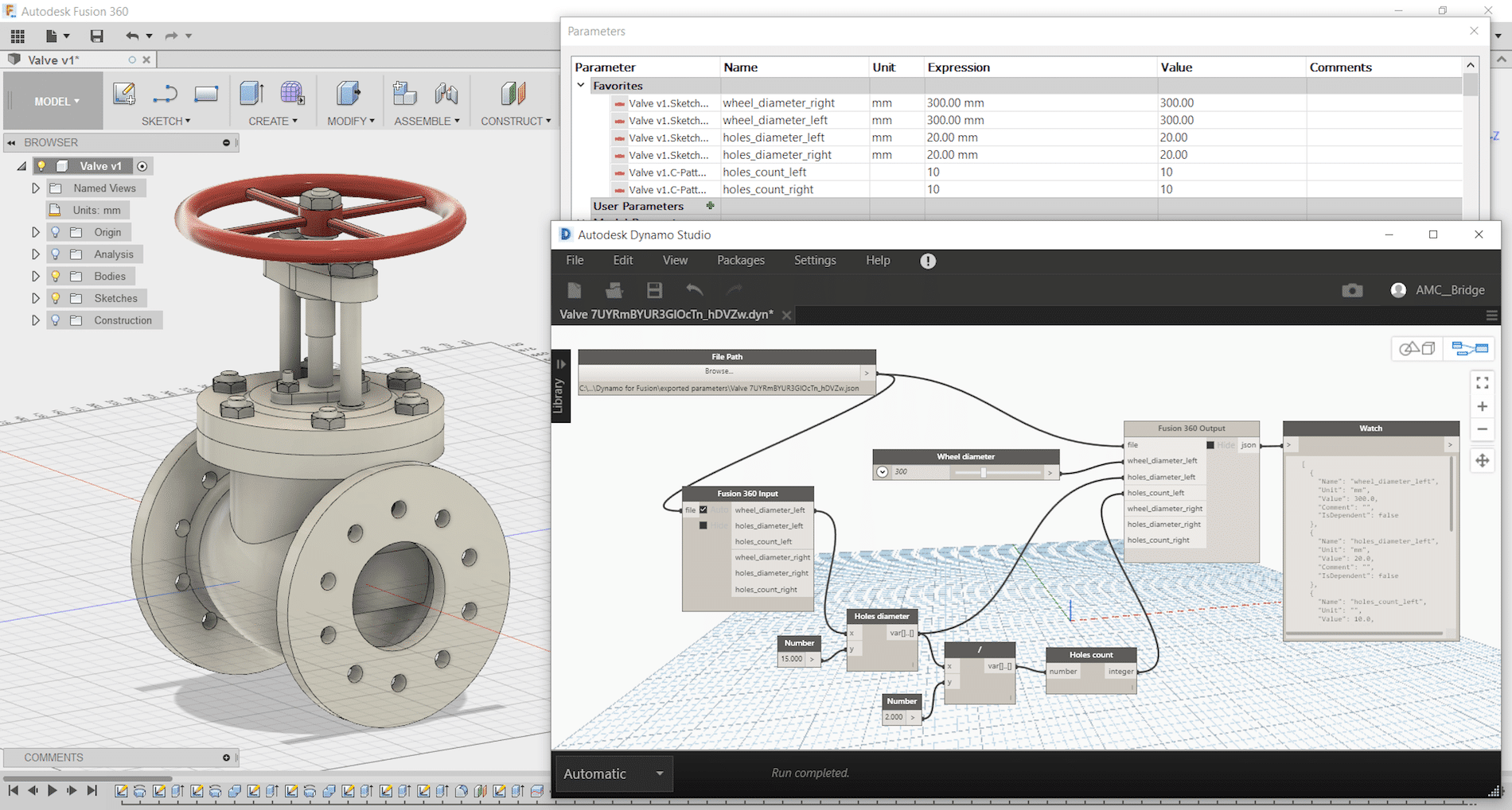
    Dynamo Studio is typically associated with Revit; however, it offers a fantastic platform for algorithmic-driven design and easy parameter manipulation in Fusion 360. It also features great T-spline and surface support for complex geometry creation, for those wishing to bring a degree of parametric control to their surfacing with ease.

    The add-in supports a bi-directional data exchange between Fusion 360 and Dynamo Studio, allowing users to create visual logic for Fusion 360 parameters update. It can be downloaded here: https://apps.autodesk.com/FUSION/en/Detail/Index?id=74731490955641349&appLang=en&os=Win64

    It provides an ability to use a visual editor environment to modify Fusion 360 model parameters, view and use them in complex logical graphs. Fusion 360 parameters will be automatically updated from Dynamo Studio using custom input and output nodes.
    Dynamo for Fusion 360 Supports Dynamo Studio 2017 version: 1.1 – 1.3.

    The benefits of using Dynamo with Fusion 360 are:

    • Very complex and rapidly reconfigurable T-Spline surfacing is
    • Parameter driven components can be modified live using sliders to adjust
    • Parameter driven components can have logic integrated to link different parameters and make automatic adjustments according to conditional
    • Parameter driven assemblies can be modified live and can adapt if setup
    • Parameter driven assemblies can have logic integrated to link parameters from different components to respond to changing geometry according to conditional

    One of Dynamo – Fusion 360 Workflows is called “Synchronous workflow”. It is directly manipulating parameters listed in the parameter table in Fusion 360. This can enable rapid reconfiguration of assemblies and components by using sliders, or logic can be incorporated to describe relationships between geometry. If you have not tried, here are some simple steps to try:

     Step 1: Create a simple Fusion part with some name parameters as shown:

    Step 2: Save and name the part as “Dynamo-Fusion”

    Step 3: Go to Tools -> DYNAMO FOR FUSION to run Dynamo


    Dynamo will create a same name parameter file with extension “.json” that contains all extracted parameters from Fusion 360 part and stored under:  C:\Users\ (your username) \AppData\Roaming\Autodesk\Autodesk Fusion 360\API\AddIns\Dynamo for Fusion\exported parameters\

    Step 4: In Dynamo’s search bar, search for “output” and insert “Fusion 360 Output” node. Repeat search for “Slider” and insert “Number Slider” node.


    Step 5:
    In Dynamo, connect File Path to “Fusion 360 Output” and “Number Slider” to any parameter and set Min, Max and Step. Use the slider to size or adjust the features.


    If you would like to manipulate other parameters, then just add more sliders. Simply select the slider node and use Ctrl+C to copy and Ctrl+V to paste it. After that you can customise each slider values (Max, Min, Step) and connect it to any of the parameters and watch the part update. You can even connect a slider to more than one parameter (i.e. to make a square cut).

    Using Dynamo with Fusion360 can be fun and simple. Try it and have fun with Dynamo for Fusion 360.

    HSM CAM Tips and Tricks: Equation-Driven Parameters

    I will be publishing quick Tips and Tricks regularly to help make you more productive and to capture your best practices.

    One of my favorite such tricks is using “smart fields” or equation-driven parameters.

    Virtually all fields in the CAM interface that accept numerical values can also accept equations that reference constants or reference other parameters/fields. Right-clicking on the field and selecting “Edit Expression” brings up an input box wherein you can enter a constant value or build at equation. Once you are done, right-click again and select “Make Default” so that this change is remembered the next time you use this machining strategy again.

    An example where a constant might make sense is plunge feed rate for operations other than drilling operations. Indeed, this is an approach speed that is largely independent of tool type or size. Perhaps you want this to always be a nice and slow 20 IPM until the program is proven safe. Stock-to-leave is another parameter that could be set to a constant.

    Referencing another parameter introduces more power. For example, several parameters can be made dependant on the cutting feed rate.

    Indeed, you can set the lead-in and lead-out feed rates to vary proportionally with the cutting feed rate. Similarly, the reduced feed rate for inner corners specified under “Feed Optimization” should also vary proportionally with the cutting feed rate defined under “Feed and Speed”. An expression referencing cutting feed rate would look like this:

    (tool_feedCutting * 0.5)

    Several parameters can be made dependent on the tool diameter. Indeed, stepovers and stepdowns are prime candidates, as are lead-in/lead-out segment definitions, spiral entry diameter, and stock-to-leave values. An expression referencing tool diameter would look like this:

    (tool_diameter * 0.5)

    Finally, expressions can contain logic and can combine the two approaches described above.

    For example, stock-to-leave might be controlled by an expression that considers tool diameter, but defaults to a minimum value below a threshold tool diameter.

    (tool_diameter >= (.250in) ? (tool_diameter * .05) : (.010in))

    Expressions can be as complicated as you can make them. They just need to respect JavaScript syntax.

    A complete list of parameters that can be used in expressions is found here: https://airtable.com/shrggXZ4wpuGUiN3w/tblJ9PHav1NwMmqMz/viw09jWqXAR0JmPPM?blocks=hide

    Investing two hours into setting up expressions for various machining strategies can go a long way towards capturing your best practices and automating HSM CAM, resulting in increased programming consistency and decreased programming time.


    Interested in tweaking an HSM (Inventor CAM, Fusion CAM, HSMWorks) post-processor yourself?

    The “SolidCAD Universal FANUC” post processor (free on our website) contains a large number of parameters that can be set on-the-fly through the “Post-Process” dialog, without needing to change anything inside the post-processor.

    If you require other changes, SolidCAD offers a post-processor modification service to adapt this post to your machine and to your best practices. If you wish to make changes yourself, you are free to do so. Indeed, the “SolidCAD Universal FANUC” post-processor and all the post-processors available on the HSM Post Library website are unlocked and open-source.

    The HSM Post Library is found here: https://cam.autodesk.com/hsmposts

    A post .cps post-processor file is merely a text file. It can be opened and edited in Notepad or any other text editor. There is unfortunately no user interface; changes must be made to the code in JavaScript language.

    However, the good news is that Autodesk publishes a free manual to guide you through the process, covering the basics of JavaScript and explaining the various sections of a post file. The manual can be downloaded here: https://cam.autodesk.com/posts/posts/guides/Post%20Processor%20Training%20Guide.pdf

    If you can’t find an answer in this 200-page guide, you can consult the vast archive of the HSM Post-Processor Forum, and even post your question on this very active forum. The forum is located here: https://forums.autodesk.com/t5/hsm-post-processor-forum/bd-p/218

    Do you know about Adaptive Clearing?

    Hey CNC’ers!

    Do you know about Adaptive Clearing? It’s the intelligent roughing strategy at the heart of HSM CAM that has changed milling forever. Increase your profitability by getting to near-net-shape in a single, highly-efficient, tool-sparing operation.

    To learn more about the advantages (as well as pitfalls) of this game-changing technology, download the following article: https://www.solidcad.ca/wp-content/uploads/2019/05/A-few-words-on-Intelligent-Roughing-by-Louis-Martineau-.pdf and visit here.

    You can also watch the video down below:

    PART 3 : Change Management (ECR, ECN, and ECO)

    This is the third in a three-part series of Fusion Lifecycle videos. In this video, we will focus on Change Management with a specific focus on Engineering Change Orders.

    In the previous video, we saw that the Bill-of-Materials was automatically extracted and transferred to Fusion Lifecycle for additional analysis, modification, export and so on. At a future point in time, someone may recognize a problem with an item in the Bill of Materials and wants to initiate a change. In Fusion Lifecycle, they can log a Problem Report. The Problem Report flows through a structured workflow becoming an Engineering Change Request(ECR) and then an Engineering Change Order (ECO).

    When the ECO is approved, Fusion Lifecycle pushes the information back to Vault, where the impacted assembly is changed to a Work-in-Progress state. Designers can then make the necessary design changes and Release the revised assembly.

    PART 2 : Bill of Materials (BOM) Transfer from Vault to Fusion Lifecycle 

    This is the second in a three-part series of Fusion Lifecycle videos. This video, will focus on the Bill-of-Material transfer from Autodesk Vault Professional to Autodesk Fusion Lifecycle.

    Vault Pro and Fusion Lifecycle can be integrated allowing data to move between the two systems. When Designers and Engineers have completed their work in CAD and Vault Pro, they will Release the assemblies.  The Bill-of-Materials is then extracted from Vault and transferred to Fusion Lifecycle as an Items BOM.  In Fusion Lifecycle, the BOM can be managed by adding or removing items.  When complete, the BOM is advanced to the Approval Stage using Fusion Lifecycle’s Bill of Materials Management capabilities.

    PART 1 : New Project Introduction Process In Fusion Lifecycle

    This is the first in a three-part series of Fusion Lifecycle videos. In this video, we will review the New Product or New Project Introduction process in Fusion Lifecycle.

    Fusion Lifecycle and Autodesk Vault Professional can be integrated to streamline the Project creation process.  In our example, we will begin by creating a project in Fusion Lifecycle.  Upon approval, Fusion Lifecycle will then automatically create that project in Vault, complete with our defined folder structure.

    Check out how SolidCAD helped Cithara Guitars Inc. make beautiful music using Autodesk Fusion 360!

    PROJECT PROFILE

    If you are inquiring about a product that does it all when it comes to product design, Fusion 360 is the solution for you!

    This 3D cloud-based platform allows users to test both fit and finish, create photorealistic renderings and simplify the production process overall. With this software you can now efficiently fabricate your designs using a CNC mill.

    Recently SolidCAD directed Cithara Guitars Inc, a custom guitar shop located in Hamilton, ON., to Fusion 360.  With Autodesk’s Fusion 360, Cithara Guitars was able to completely design and manufacture their guitars in one environment without any rework or errors