• Importing wire types in AutoCAD Electrical

    Figure 1

    Whenever we are working with AutoCAD Electrical, one of the key features that we have when we are creating our drawings, is the ability to

    create and assign the custom wire types that we will use throughout our schematic designs. Every time that we create a new drawing, by default the only wire that is going to be available is the WIRES layer which is the generic wire type that the software uses when we first create any type of wire as displayed on Figure.1 in the Create/Edit Wire Type editing window.

    Having to manually enter the types of wires that we are going to use is a task that cannot be avoided the very 1st time that we create a drawing, but once we having created the list of wires that we need to use in one drawing, we can reuse them over and over again.

    To achieve this we need to do the following:

    • Open the Create/Edit Wire Type editing window and click on the icon that says “Import” as seen on Step 1 on Figure 2.
    • A window will pop-up asking you to browse to the drawing that contains all the wires information, browse to the desired drawing.
    • Once we have selected the DWG another window will pop-up displaying all the wires from that drawing.
    • By default all the wires from that drawing are selected and highlighted in black as seen on Step 2 on Figure 2.
    • We can pick and choose the wires that we want to import and the click OK to complete the process.

    Figure 2To take this one step further, we can standardize the wires that we use with your CAD Manager so we can import that list of wires directly into your templates. To achieve this we need to open the current template as a DWT file, then repeat the exact same process that was described earlier.

    Once we have completed importing all the wires we need to re-save the template as a DWT one more time to make sure it will be usable as a template in the future.

    This will further standardize the wires that the designers are required to use and remove the guess work by setting the wires at a template level.


    Getting Started with Product Design Visualization

    Getting started with product design visualization is easy.

    Currently most engineering is accomplished using 3D modeling software’s. It can be done in solids, surfaces, meshesnurb curves etc. It can be done as freeform, sculpted, parametric design, AI driven even. The possibilities are endless. 

    Still, somehow, it’s a common misconception in the manufacturing community that product design visualization is a niche discipline and is out of reach. Many companies even think that their products don’t require any type of product rendition because they are not doing consumer products. The fact is, that technologies and 3D models are so common and easily available now a days, that it is assumed by consumers that products are available to view on demands. One would expect to go on a manufacturer’s web site and view catalog products. That goes for any type of products, even heavy-duty industrial machinery. Lacking in product showcases can leave a diminished and negative perception of quality and services by a typical buyer. If people buy with their eye’s, setup a digital photo studio and give them eye candy.

    As the title of this blog implies, getting started with product design visualization is easy. In all Autodesk Collection of software’s is included 3DS Max. 3DS Max is an industry standard for 3d modeling, animation, special effects and obviously rendering. It’s comprehensible that at first glance such a software can be intimidating with the thousands of tools and features. Many users opened it just to close it immediately in fright after seeing the user interface. But when it’s come to basic visualization you will only need a hand full of those features. The workflow for a basic Photo studio style visualization is as easy as this:

    1. Import your model​
    2. Adjust materials to taste ​
    3. Set up environment​
    4. render 

    1. Import your model

    3DS Max support lots of different file types. The list shown here cover lots of ground and enable easy and efficient importation from any provenance.

    2. Adjust materials to taste

    The simplified material editor (Compact mode) is simple to use. I strongly recommend using the physical material since these materials have built in templates for quick creation and those materials are compatible with most renderers.


    3. Setup Environment

    In the environment dialogue box, a high dynamic range image can be imported as the scenes background. Those HDRI images do not only

    act as the scene environment but also act as the lighting scheme for the scene. This makes lighting a scene with the desired look a breeze. The high dynamic range image can also be used only as light. The actual environment don’t have to be shown to light the scene so another image can be used as a background. Having real lighting with a backdrop type background creates an excellent studio photoshoot space. 3DS Max come bundled with dozens of High dynamic range images but these images can be easily found by the thousands on the web.


    Scene without lights
    Scene with HDRI environment lighting
    Same scene with Studio backdrop

    4. Render

    From there you can render from the viewport as a point and shoot type of work. Cameras can also be created for more control and repeatability. To prove my point, I have done more examples of studio photoshoot style render’s. We can clearly see that this type of rendering is very suitable for manufacturing and industrial products and won’t break the bank.

    The learning curve of achieving your first renders with 3DS Max is not steep at all!

    Basic software file management, navigation and manipulation are the same as any other software and those knowledges are transposed with no effort. Learning how to set the environment dialogue box, how to use the material editor and how to adjust cameras will require a little work, but not much.


    Ask your Sale’s representative at SolidCAD about our new 2 days training; 3DS Max – Photo Studio Rendering.

    Bring your 3D design to life with 3DS Max.

    Effective Data Structure is Key for Success in Today’s Digital Workplace

    Digital transformation is essential for any business looking to navigate the post-COVID world that exists today. Before the pandemic, the focus on digital transformation was high but has increased due to a large portion of the labor force relying on easily accessible data at home. 

    At the heart of any successful digital transformation project is accurate data structure. 


    What Is Digital Transformation? 

    Digital transformation refers to the process of shifting operations, data, and tools commonly available in offline or non-interactive environments to a completely digital solution. Digital transformation can yield the following benefits: 

    • Increased visibility to data trends will lead to an improved understanding of the customer experience and an uplift in sales 
    • Provide reports that highlight improvement opportunities within common workflows that reduce costs and increase efficiency 

    While the benefits of digital transformation have been on display for many years, some businesses view this practice as a lower priority. Specifically, asset-heavy organizations are reluctant to change and move their information online or revamp their technical infrastructure. Instead, these businesses prefer to continue maintaining older and outdated systems to minimize the impact on existing day-to-day operations. 

    How COVID-19 has Pushed Digital Transformation to the Forefront

    With the onset of the pandemic, organizations have needed to scramble to enable remote operations, social distancing, and continue to maintain assets across multiple sites and locations. Suddenly digital transformation is now a requirement for many businesses. 

    This has been a difficult transition period for organizations that didn’t have an existing plan in place. Effective data structure has emerged as an essential piece of this transformation.  

    Digital Transformation is Built on Strong Data Structure 

    Well governed and structured data is the basis of a well-executed digital transformation. The amount of data can be overwhelming for asset-heavy organizations and found in different sources such as: 

    • Work orders 
    • Asset data and maintenance records 
    • Data coming in from various other mission-critical tools – i.e., EDMS or CMMS solutions 
    • MRO inventory data 
    • Pen and paper documentation 

    Unstructured Data Can Lead to Long Drawn-out Digital Transformation 

    Most organizations have their data spread over different locations and tools. This data can also be inaccessible by various teams and generally unstructured. Here are a few reasons why: 

    • Knowledge is often spread by word-of-mouth with no documentation available 
    • Data consists of a combination of paper, on-premise, and cloud-based tools. This inconsistency leads to incomplete information, poor document version control, and more 
    • Existing digital solutions work independently of each other with little integration 
    • Day-to-day digital workflows are not standardized or governed for good data structure 

    Incomplete Data Leads To Poor Asset Structure 

    If your asset-intensive organization has poor data quality, this will affect your asset structure. All the information surrounding an asset (i.e., documentation, compliance, maintenance plans, etc.) will be affected by default, which can lead to: 

    • Incomplete data sets 
    • Out-of-date information 
    • Trouble maintaining industry compliance 
    • Higher costs to maintain data infrastructure 
    • Data security issues 
    • Increased risk of a digital transformation project failing 

    Once a weak data structure exists, the related issues will carry over into other complementary solutions. The lack of robust and available data will affect other data-driven automation and Industrial Internet of Things (IIoT) projects. These solutions require a complete and comprehensive data structure to build and implement successfully. 

    How to Ensure your Data and Asset Structure is Correct 

    To set up your business for a successful Digital Transformation, you can improve your data structure by focusing on accurate data, robust data structure, and data governance. 

    1. Review Your Current Data

    Reviewing your current data should be the first step for improving the existing data structure. This requires that you answer vital questions about your data itself, including: 

    • What data do you have? 
    • What information are you collecting regularly? 
    • How and where is the data used? 
    • What does that data tell you about your customers, about your KPIs, about your business? 
    • Identify missing data opportunities. Where are there currently gaps in your data needs? 

    Leading off with a review of current data will help your team understand your data and what you do with it. 

    2. Organize your Data with the Appropriate Tools

    The next step is to use a well-structured tool to import your data. Using a tool that can assist with proper data structure, governance, and analytical insights will ease your path to digital transformation by: 

    • Providing automation of workflows to increase data entry efficiency and ensure data accuracy by avoiding human error 
    • Confirming your data initiatives are standardized and repeatable 
    • Guarantee that your organization can easily manage your information’s flow, quality, and governance, which is key to any compelling insights or transformation efforts 

    Selecting the right solution will vary by your organization’s industry, data sources, and required integrations. The right tool will provide a broader view and understanding of your data as a whole to your entire team. 


    What Types of Tools fit best For Asset-Intensive Organizations? 

    Two tools covering these requirements are a computerized maintenance management system (CMMS) and an electronic document management system (EDMS). Ideally used together, an EDMS and CMMS solution will work in sync and provide increased functionality as a whole. 

    Most successful asset-heavy organizations already use a CMMS or EAM solution for their maintenance tracking needs. It allows you to digitize and automate maintenance operations to deploy preventive maintenance strategies better, develop better maintenance practices, stay organized, and ultimately save time and money. While this is a significant first step into modernizing your digital data footprint, a CMMS system alone is missing essential functionality for maintaining your data structure in other areas (i.e., technical drawings and documentation). This functionality is where an EDMS solution excels. 

    Pairing an EDMS with a CMMS solution is the winning combination that empowers your team with the following benefits: 

    • A fully connected digital single source of truth with high availability 
    • Automation across multiple tools to improve efficiency and data accuracy 
    • Easy to manage data governance over the entire technological stack 

    In a post-COVID world, organizations that complete digital transformations and modernize their operations will pull past competitors relying on legacy systems. But making the transition begins with reliable data and solid asset structure as a first step. 

    To learn more about Meridian solutions (EDMS and CMMS) and how they can help your team, don’t hesitate to get in touch with the SolidCAD Meridian team.  

    Understanding Product Lifestyle Management (PLM): The Path to the Digital Future

    In my opinion, the most painful product lifecycle management (PLM) failures happen when companies struggle to understand the concept and implement it in their organization. This technology is made to help them. When I speak to companies, I hear things like – “We tried to organize ourselves, but PLM was such a complex idea. We decided to stay unorganized.” It hurts me to think about the failures of technology despite the powerful idea of PLM.

    I want to focus on explaining why you need PLM and how to identify if it can help support your product development and manufacturing operations. Understanding this will help you get prepared and organized for the digital future.

    CIMdata defined digitalization as “The business strategy best geared to extract real-world value from digital data”, whereas their definition of PLM refers to a “strategic business approach, NOT just technologies, a consistent set of business solutions”.

    I’ve noticed a growing interest in product lifecycle management and its benefits in the last year. As companies look to improve their product offerings, refine supply chains, and organize their business, PLM is one of the best tools to achieve these goals.

    When implementing PLM, your organization should be setting goals and KPIs regularily along the way. Our software will allow you to collaborate with SolidCAD and suppliers to integrate important data from their end as you assess each step in your process.

    As your organization goes through each of these stages, you should be collecting and entering data into your PLM software. We will help you streamline the process and allow you to eliminate tedious data re-entry. This means that your PLM software should smoothly integrate with your enterprise resource planning (ERP) system.

    You may be wondering why PLM is important for our digital future. Expected results for companies using PLM software include:

    Lower product costs:

    PLM is an iterative process that your organization will refine with each cycle, one of the most common goals is to lower production costs. This may seem intuitive for any company that engages in product development, but it’s important to point out that PLM achieves this by creating a more refined supply chain along with a streamlined production process.

    Greater product quality:

    In a similar artery to lowering product costs, product quality should increase as you foster the PLM process. Whether it’s finding more diverse materials or better parts at the right price, each cycle should push you to assess your sourcing, development, and production methods to improve your offerings.

    Faster time to market:

    This is a direct result of improving your supply chain along with manufacturing and logistics. PLM is not only a about single product throughout its lifecycle; it is a tool to have comparable data that allows you to streamline and improve the steps in your process.

    So, what does PLM currently offer? PLM provides a central repository of accurate information that geographically dispersed personnel can access. In a post-2020 world where more and more teams are working remotely, there’s undeniable value in this system that facilitates accurate data sharing and collaboration don’t you think?

    To summarize, here are the 5 main reasons that you will need PLM based on my knowledge and conversations with customers:

    1. Increased productivity: PLM facilitates the process of lifecycle management and drives improvements across the series of cycles for the given product. Implementing a scalable PLM platform increases employee productivity by consolidating designs, communications, workflows, and product data in a single place.
    2. Accelerated time to market: The smoother the workflow and the higher the productivity, the faster your organization will be able to bring products to market.
    3. Increased revenue: As you accelerate your time to market with PLM, you’ll also be reducing production costs. The intersection between those two actions will improve your margin and help you scale up your business. You can’t just think of PLM as a way of improving workflows; one of the most critical KPIs after a few cycles is how it is impacting your revenue.
    4. Accurate data sharing: PLM organizes your data, helps you keep track of it, and allows for sharing with the right stakeholders at the right time (both internal and external).
    5. Improved product quality: More accurate data and improved workflows are always going to lead to improved product quality. I believe, that is another contributing factor to increased revenue. Regardless of an organization’s position in the supply chain. That stands for both business and commercial transactions. As you refine your PLM steps and drive even minor improvements, you’ll see the difference in the product for sure!

    From a business development representatives’ point of view to you, I can assure you that lifecycle management issues can be found across small, medium, and large business. When it comes to growing and improving your company, PLM solutions are the digital future.


    Get in Touch:

    If you made it this far in reading, you’re probably ready to get started on the path to the digital future. Learn more on our website: https://www.solidcad.ca/products/autodesk-products/product-lifecycle-management/

    If you prefer to get in touch with us directly, please contact myself and my team at tanya.petraglia@solidcad.com for more information, or meet our team at upcoming events: https://www.solidcad.ca/product-lifecycle-management-events/


    Tanya PetragliaBusiness Development Manager – Helping customers connecting processes with PLM- Manage 360

    Migrating Versions in AutoCAD Electrical

    Every year Autodesk releases a new version of the software which often contains new features, bug fixes and overall improved stability, so a common question that we get from our customer is: how do I move all my custom settings, symbols, databases, etc. to the new version of AutoCAD Electrical. Included with AutoCAD Electrical is the “Migration Utility” which allows the user to move all your customized settings, custom libraries (symbols + icon menus), databases, etc. This utility can be found inside the “Project” tab as displayed on Figure 1.

    Figure 1

    In this blog article we will cover the steps requires for us to upgrade and migrate from one version to another. Once we have downloaded and installed the new version of AutoCAD Electrical, we close all other Autodesk software that so we can start the “Migration Utility”.

    Figure 2

    In this configuration window we are required to select the previous version that we want to migrate from. Clicking on the dropdown arrow will display all the previous versions installed on the local machine. If you have more than one version installed, you need to select the software version that has all the latest customization/libraries of the software as seen on Figure 2.

    After we select the version that we want to migrate from, the next step is to select the items we want to migrate. Those items can be found under “Migration items” and, by default, all of them are going to be selected as seen on Figure 3. If we click on any of the individual items, we will find the option to copy or merge the pre-existing information. Keep in mind that each migration item might have a different preset value here so make sure you review all the items that need to be migrated.

    Figure 3

    Once we have reviewed all the migration items we need to click “OK” so the migration process can start.

    Figure 4

    Before the migration gets started, a “Migration Review” window is going to popup with a summary of all the files that are about to be migrated as seen on Figure 4.

    After a final review we are ready to click “OK” so the migration process can start.

    While the migration is in progress, a window is going to popup showing the file currently being migrated and the current progress status as seen on Figure 5. Keep in mind that depending on the size of your customized files (databases, etc.), this process could take from minutes to several hours.

    Figure 5

    When the Migration is complete a summary window similar to the migration review will popup specifying, once again, all the files that were migrated.

    The last step is to restart the software so you will be ready to use your new version of AutoCAD Electrical without losing any preexisting customized files/settings.

    Autodesk Fusion 360 & Metallic Strip Animal Sculptures – Part 1

    Part 1

    I love sculptures and can spend hours at museums that devoted to sculpture. I also love structural Engineering and structural sculptures. Running into Artist Sung Hoon Kang‘s stunning animal sculptures that embody the movement, speed, and chaotic energy of the wind, fascinated me. You can take a look of his work here: Metallic Strip Animal Sculptures Radiate the Energetic Flow of Wind:  https://mymodernmet.com/kang-sung-hoon-sculptures/ Sung Hoon Kang‘s works got into in my head and made me think of how I can use Autodesk’s products such as Fusion 360 or 3DS Max to create/model these sculptures. I know Fusion 360 can combine organic shapes modelling, mechanical design, and manufacturing in one comprehensive package, but can it be used to create/model these kind of art works?

    The question stayed in my head until I found a possible solution by combining Fusion 360 and 3DS MAX. After finding the approach and workflow, I created the concept models of two metallic strip animal sculptures of a dog and a horse, and posted them on Fusion 360 Gallery. You can find and download my two metallic strip animal sculptures here:

    https://gallery.autodesk.com/projects/141060/fusion-360-for-art-work—-horse-metal-strips

    https://gallery.autodesk.com/projects/141004/fusion-360-for-art-work—dog-metal-strips

    Believe it or not, once you find a good workflow between 3DS MAX and Fusion 360, You can create these animal sculptures in 20 minutes or less.

    Here is how:

    Step 1Understanding Fusion 360 Freeform Tools

    You should know that Fusion 360 is not just an awesome freeform modeler; it is also a parametric modeler. Fusion T-Splines are a combination of NURBS and Subdivision modelling that was developed in 2003.The T-splines company was bought by Autodesk and was built into Autodesk’s Fusion 360. The T-Splines subdivision surface technology in the Freeform toolset make it easy to create completely smooth, curvature continuous, ‘Watertight’ NURBS surface models, that you can convert to Solid models.

    Fusion 360 Freeform tools are very helpful when you want to create an organic surface without having to spend lot of time planning and executing individual surface patches. T-spline surfaces are simple and intuitive, and it is really easy to iterate through a number of different options.

    Step 2Understanding 3DS MAX Polygon modeling

    Polygon modeling is more common with game design than any other modeling technique as the very specific control over individual polygons allows for extreme optimization. Usually, the modeler begins with one of the 3ds max primitives, and using such tools as bevel and extrude, adds detail to and refines the model.

    Fusion 360 loves Polygon modeling objects and it can quickly convert those objects into solids for you if needed.

    There are two kinds of mesh that you can import into Fusion 360; however, only mesh that came from Polygon objects can be converted to solids.

    To covert triangulated mesh to solid, it needs to be converted to Editable Poly before inserting into Fusion 360. These are the steps:

    • Import triangulated mesh into 3DS Max
    • Apply Subdivide (WSM) with “Display Subdivision” turn OFF
    • Use “Collapse To” to Collapse mesh
    • Turn Collapse mesh to Poly mesh
    • Apply “Quadrify All”.

    Step 3Understanding 3DS MAX Particle Flow

    Particle Flow is a versatile, powerful particle system for 3ds Max. It employs an event-driven model, using a special dialog called Particle View. In Particle View, you combine individual operators that describe particle properties such as shape, speed, direction, and rotation over a period of time into groups called events. Each operator provides a set of parameters, many of which you can animate to change particle behavior during the event. As the event transpires, Particle Flow continually evaluates each operator in the list and updates the particle system accordingly.

    Particle Flow provides several tools for determining where in the system particles currently reside, including the ability to change particle color and shape on an event-by-event basis. You can also easily enable and disable actions and events and determine the number of particles in each event. To speed up checking particle activity at different times during the animation, you can cache particle motion in memory. Using these tools, plus the ability to create custom actions with scripting, you can create particle systems of a level of sophistication previously unachievable.

    To create a Particle Flow, you need to place a PF Source and assign the PF source to an object. I used a dog model as an example to illustrate the use of PF source in this GIF image.

    Step 4Saving Particle Flow trails and Export them to AutoCAD

    You can make Particle Flow to generate animated Splines and save Particle trails. The animated Splines can be exported to AutoCAD format to be used for creating structural model or Poly mesh that will be turned into solids using Fusion 360.

    Step 5Creating Metallic strips from exported AutoCAD file

    The AutoCAD file can now be imported back into 3DS MAX. You can turn all the splines into Polymesh by simply turn on the ‘Enable in Viewport’ under Rendering option. In my example, I chose “Rectangular” option with Length =15mm and Width = 3mm

    At this stage, the model may require some modification for different strip thickness or clean up according to the artist’s design. Whenever you are ready, you can then export the entire MAX model out as a OBJ format to bring into Fusion 360 for fabrication.

    All Splines with rendering thickness property can now exported to OBJ format for Fusion 360 to convert to solids.
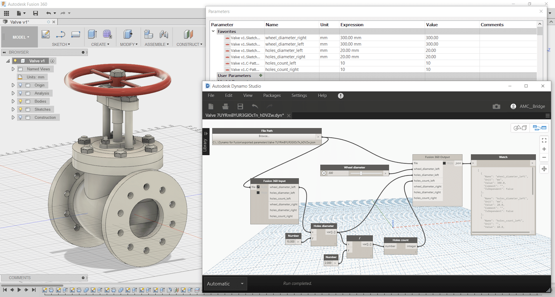
    Step 6Creating Metallic strips and complete the model in Fusion

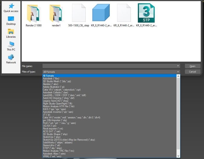
    This step is very simple. There are various Insert commands you can use to insert other file formats. These options insert data into a current Fusion 360 design rather than opening the existing Mesh (STL or OBJ format), SVG, or DXF file. Refer to the following links for more information about inserting meshes, DXF, and SVG files into Fusion 360 designs: How to insert a mesh body into Fusion 360

    The next step is converting a mesh body to a b-rep or t-spline body in Fusion 360, the current limit for number of mesh elements is roughly 10,000. Meshes with greater than 10,000 elements will cause the performance of Fusion 360 to suffer and Fusion 360 may not be able to convert them to solid bodies.

    On my next blog, I will discuss and share with you some tips and tricks on how to convert mesh body to a b-rep or t-spline body in Fusion 360.

    You can also find me on AU 2020 by following this link and search for ‘Hung Nguyen’

    Until next time…

    Tons of new goodies for Fusion 360 CAM

    Since I last wrote here, there have been big, big changes to Fusion CAM (excuse me: “Fusion Manufacturing”). These changes range from completely new (and it needs to be said, very useful) machining strategies, to significant progress in the implementation of probing technology, to new love for turning, and to subtle but much-appreciated improvements to the user-interface.

    The biggest changes are contained within the Manufacturing Extension, a new subscription add-on for Fusion CAM. The idea is that while Fusion CAM (and Inventor CAM and HSMWorks, for that matter) is a modern and very competent CNC programming solution that can make short work of most jobs at a VERY attractive price, there are some customers that require still more power and that are willing to pay a little extra for it. Mold makers are a good example. In the past, the limited multi-axis toolpaths of Fusion CAM did not quite meet their needs. With the new Steep-and-Shallow strategy as well as toolpath trimming / direct editing (both technologies gifted from PowerMill), that has all changed. The Manufacturing Extension also opens the door to surface inspection and on-machine verification, a very hot button for anyone trying to increase efficiencies and get an advantage. Throw in automatic hole recognition technology (thanks, FeatureCAM) and a new Rotary multi-axis 3D milling strategy (this one is all Autodesk), and there is something for everybody. How much for these new goodies? 125 Cloud Credits ($125 USD) per month, month-to-month.

    And those other improvements? How about a new tool library interface? The old one definitely was a little clunky. And for those of you who make extensive use of user-templates to capture their best practices (why isn’t everybody?), how about a new interface that will allow you to sort and better manage everything?

    I haven’t talked about turning yet… It can be said that while Fusion CAM  / HSM CAM has traditionally been a competent turning solution, most of the R&D over the years has gone into making it a premier milling solution. But a dedicated turning team has now been brought into the development team, and turning is now getting the love it has always deserved. In my next blog, I’ll list all the recent changes (it’s a very long list of small but significant changes). What’s more, we are promised many more such improvements throughout the year, including something called Adaptive Turning that sounds very promising.

    Please note that the Manufacturing Extension is free to use right now through June 2020. So, by all means, give it a spin! Several of the other new features are available through the preview mode: just activate what you want under Preview Features in your Preferences; everything is quite stable.

    Now, it is quite apparent that Autodesk is turning Fusion into its premier CAM solution. That’s great news and we welcome all the improvements to an already-great CAM. However, if you are a user of Inventor CAM (or HSMWorks), don’t hold your breath for things like Steep-and-Shallow. Instead, Autodesk would rather you fire up the Fusion 360 entitlement included with your CAM. And to make it easier to use two platforms in parallel, recent changes now allow Fusion to play extremely well with Inventor and even SolidWorks.

    Sharing is Caring

    In todays manufacturing world there is a bigger demand on sharing data with all stakeholders outside your company.  This could be your supplier, buyer, manufacturing team and they could require viewing the drawing to the 3D model that you create.  Using Autodesk Vault you can created a shared view for your outside stakeholders and value chain.  Autodesk provides this as a free viewer, markup and comments, all they would need to do is sign up for a free Autodesk account.  Also Share View is a great tool to use internally as well to do digital markups and collaboration outside the engineering department.

    To use Share View simply log into Autodesk Vault and find the model or drawing you would like to share and right click and select Share View:

    You may be prompted to login using your Autodesk account, once you have logged in the Create a Shared View dialog box will prompt you to enter a name:

    Enter the name you would like and then click on Share, and it will start to process the shared view.

    Once complete a Share View Complete Dialog will display that it was uploaded successfully and it will give you a copy link and view in browser option.

    Copy Link – This is the link you can email to your stakeholders for them to open and view online.

    View in Browser – this will open the shared view in your browser for you to view.

    Clicking on View in Brower it will launch the Share View online:

    This view will only be available for 30 days on Autodesk Viewer.  Only users who are invited though the link or when selecting share will have access to the model or drawing.

    Once singed in users can markup, add comments and when clicking on share, it will send the users in Vault a notification that someone has made a comment on the drawing.

    To make a comment simply select comments to type a comment directly.  Anytime you click on Markup the markup changes will be saved on the comments tab when you select Post.


    In Vault client to view the comments or markups make sure that Shared Views Panel is turned on.  If not turned on simply go to View > Shared Views and make sure there is a check mark beside Shared Views:

    In the Shared Views panel the comments and markups will be shown:

    To make a comment back simply click on Reply and it will take you back to the Autodesk Viewer to continue the collaboration between your company and stakeholders.

    As you can see getting data to correct users at a timey manor is critical in todays business.  Autodesk Vault Professional and Shared Views enables you to connect the value chain and make sure everyone has the data they need.  Also, Autodesk viewer is not just limited to Inventor or AutoCAD drawings and models if you go directly to viewer.autodesk.com you can sign into your account and upload the following files for collaboration:


    Remember Sharing is Caring and happy collaborating!!

    Dynamo for Autodesk Fusion 360 – Made Simple

    Dynamo Studio is typically associated with Revit; however, it offers a fantastic platform for algorithmic-driven design and easy parameter manipulation in Fusion 360. It also features great T-spline and surface support for complex geometry creation, for those wishing to bring a degree of parametric control to their surfacing with ease.

    The add-in supports a bi-directional data exchange between Fusion 360 and Dynamo Studio, allowing users to create visual logic for Fusion 360 parameters update. It can be downloaded here: https://apps.autodesk.com/FUSION/en/Detail/Index?id=74731490955641349&appLang=en&os=Win64

    It provides an ability to use a visual editor environment to modify Fusion 360 model parameters, view and use them in complex logical graphs. Fusion 360 parameters will be automatically updated from Dynamo Studio using custom input and output nodes.
    Dynamo for Fusion 360 Supports Dynamo Studio 2017 version: 1.1 – 1.3.

    The benefits of using Dynamo with Fusion 360 are:

    • Very complex and rapidly reconfigurable T-Spline surfacing is
    • Parameter driven components can be modified live using sliders to adjust
    • Parameter driven components can have logic integrated to link different parameters and make automatic adjustments according to conditional
    • Parameter driven assemblies can be modified live and can adapt if setup
    • Parameter driven assemblies can have logic integrated to link parameters from different components to respond to changing geometry according to conditional

    One of Dynamo – Fusion 360 Workflows is called “Synchronous workflow”. It is directly manipulating parameters listed in the parameter table in Fusion 360. This can enable rapid reconfiguration of assemblies and components by using sliders, or logic can be incorporated to describe relationships between geometry. If you have not tried, here are some simple steps to try:

     Step 1: Create a simple Fusion part with some name parameters as shown:

    Step 2: Save and name the part as “Dynamo-Fusion”

    Step 3: Go to Tools -> DYNAMO FOR FUSION to run Dynamo


    Dynamo will create a same name parameter file with extension “.json” that contains all extracted parameters from Fusion 360 part and stored under:  C:\Users\ (your username) \AppData\Roaming\Autodesk\Autodesk Fusion 360\API\AddIns\Dynamo for Fusion\exported parameters\

    Step 4: In Dynamo’s search bar, search for “output” and insert “Fusion 360 Output” node. Repeat search for “Slider” and insert “Number Slider” node.


    Step 5:
    In Dynamo, connect File Path to “Fusion 360 Output” and “Number Slider” to any parameter and set Min, Max and Step. Use the slider to size or adjust the features.


    If you would like to manipulate other parameters, then just add more sliders. Simply select the slider node and use Ctrl+C to copy and Ctrl+V to paste it. After that you can customise each slider values (Max, Min, Step) and connect it to any of the parameters and watch the part update. You can even connect a slider to more than one parameter (i.e. to make a square cut).

    Using Dynamo with Fusion360 can be fun and simple. Try it and have fun with Dynamo for Fusion 360.

    HSM CAM Tips and Tricks: Equation-Driven Parameters

    I will be publishing quick Tips and Tricks regularly to help make you more productive and to capture your best practices.

    One of my favorite such tricks is using “smart fields” or equation-driven parameters.

    Virtually all fields in the CAM interface that accept numerical values can also accept equations that reference constants or reference other parameters/fields. Right-clicking on the field and selecting “Edit Expression” brings up an input box wherein you can enter a constant value or build at equation. Once you are done, right-click again and select “Make Default” so that this change is remembered the next time you use this machining strategy again.

    An example where a constant might make sense is plunge feed rate for operations other than drilling operations. Indeed, this is an approach speed that is largely independent of tool type or size. Perhaps you want this to always be a nice and slow 20 IPM until the program is proven safe. Stock-to-leave is another parameter that could be set to a constant.

    Referencing another parameter introduces more power. For example, several parameters can be made dependant on the cutting feed rate.

    Indeed, you can set the lead-in and lead-out feed rates to vary proportionally with the cutting feed rate. Similarly, the reduced feed rate for inner corners specified under “Feed Optimization” should also vary proportionally with the cutting feed rate defined under “Feed and Speed”. An expression referencing cutting feed rate would look like this:

    (tool_feedCutting * 0.5)

    Several parameters can be made dependent on the tool diameter. Indeed, stepovers and stepdowns are prime candidates, as are lead-in/lead-out segment definitions, spiral entry diameter, and stock-to-leave values. An expression referencing tool diameter would look like this:

    (tool_diameter * 0.5)

    Finally, expressions can contain logic and can combine the two approaches described above.

    For example, stock-to-leave might be controlled by an expression that considers tool diameter, but defaults to a minimum value below a threshold tool diameter.

    (tool_diameter >= (.250in) ? (tool_diameter * .05) : (.010in))

    Expressions can be as complicated as you can make them. They just need to respect JavaScript syntax.

    A complete list of parameters that can be used in expressions is found here: https://airtable.com/shrggXZ4wpuGUiN3w/tblJ9PHav1NwMmqMz/viw09jWqXAR0JmPPM?blocks=hide

    Investing two hours into setting up expressions for various machining strategies can go a long way towards capturing your best practices and automating HSM CAM, resulting in increased programming consistency and decreased programming time.