• Outil Civil 3D pour simplifier vos terrassements – CIM Project suite 2021

    L’article de blog d’aujourd’hui présentera des outils qui simplifieront vos designs de terrassement, en utilisant tout le potentiel des Lignes caractéristiques de terrain sans avoir à passer par les outils de Talus de Civil 3D.

    Cela dit, nous utiliserons l’outil Auto Grader de la suite d’outils CIM Project développée par CTC Software.

    Création de Talus par défaut dans Civil 3D, le pour et le contre

    Contre :

    • Tend à planter lorsqu’on projette en général des lignes caractéristiques de terrain trop lourdes en points d’intersections (souvent dû au drapage de ses élévations sur une surface trop détaillée);
    • Tend à planter lorsqu’on projette des lignes caractéristiques de terrain en talus vers des surfaces trop détaillées, nécessitant la simplification des surfaces;
    • Environnement de design peu visuel, et complexe dans son utilisation (comprenant la création de groupes de talus au préalable, la gestion de Sites rarement utilisés et l’élaboration de critères de talus dans le gabarit).
    • Petits bugs « anodins » présents depuis des années, comme la disparition des zones de remplissage lors du déplacement d’un projet/groupe de talus.
    • Travaille toujours en pentes fixes, bloquant certaines combinaisons d’entrées en terre, comme une distance fixe vers une surface (résultant potentiellement en une pente variable sur tout le terrain).

    Pour :

    • La création de transitions de pentes variables entre deux pentes fixes différentes est très efficace, le long d’une même ligne caractéristique de terrain.
    • Contient des outils de calculs de volumes et « d’optimisation » de design imbriqués au module de création de Talus.


    En résumé, si un sondage à tous les utilisateurs de Civil 3D demandait quel est l’outil de design le plus instable du produit, la grande majorité répondrait la création de Talus. Les « bonnes pratiques » dans son utilisation, comme la simplification des lignes caractéristiques de terrain et des surfaces de rattachement pour les entrées en terre, sont très efficaces pour contourner les « plantages », mais demande également de faire des compromis sur la qualité et la densité de notre donnée de base.


    Auto Grader, la solution à bien des maux de têtes en conception

    Vient à la rescousse la suite d’outils CIM Project de la compagnie CTC Software, avec son outil Auto Grader.

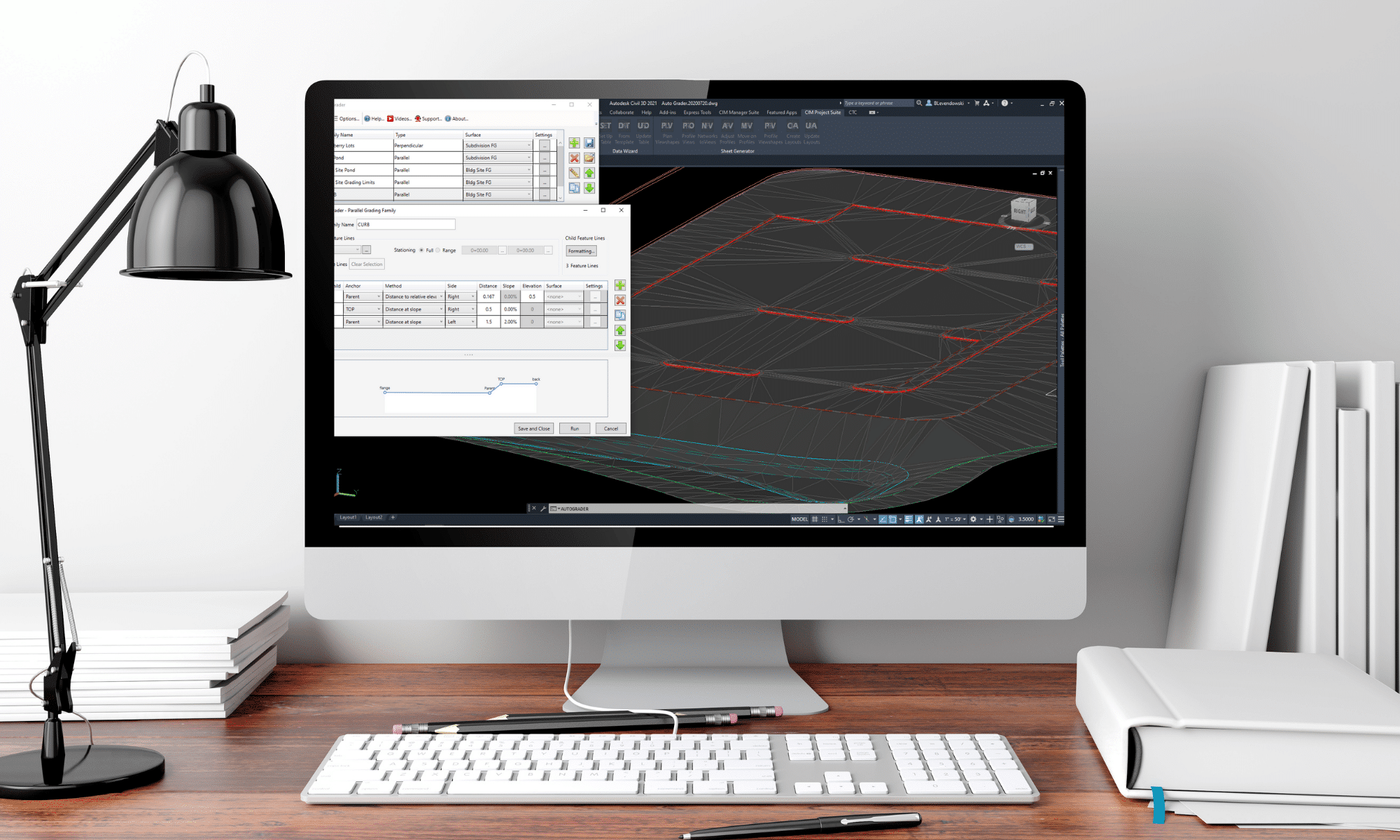
    Auto Grader est un outil de création de talus à part entière exploitant les lignes caractéristiques de terrain pour créer des designs de terrassement. Étant complètement indépendant des outils de création de Talus de Civil 3D, il a sa propre interface, ses propres combinaisons de critères de pentes et sa propre approche pour standardiser et reprendre des designs d’un dessin à un autre.

    L’interface d’accueil permet de gérer les Grading Families liées au dessin courant, et comprend notamment :

    • Leur création ,
    • Leur édition ,
    • Leur exportation en format .JSON, afin d’être partagés avec d’autres intervenants ou dans d’autres projets Civil 3D,
    • Un aperçu de la famille sélectionnée, en mode « vue de coupe »,
    • Des fonctions et paramètres d’ajout des Grading Families dans des surfaces Civil 3D spécifiées.

    Plan Production Workflow with CTC Tools: Sheet Sets

    Creating sheets has always been a time-consuming process and needs to be addressed quite early in the design for preliminary submissions.

    While sheet sets can help us with global information updates across sheets with the use of fields, they cannot alter or create layouts and viewports.

    Civil 3D does offer a solution for creating multiple sheets in one fell swoop. But, where these tools fall short is in flexibility and updating.

    CTC Software has come up with a set of tools to bridge this gap in flexibility and updating. This workflow can integrate seamlessly into a company standard with only the addition of 3 blocks and a few designated layers.

    Sheet Generator ties in with sheet sets for information updating, and has the power to update Plan & Profile sheets if the alignment or scope change throughout a project.

    Instead of View Frames spliced by matchlines, Plan Viewshapes inserts blocks as viewport area extents and closed polylines representing the actual shape of the viewports in layout sheets.

    Profile Views takes advantage of native tools to split up profiles for each sheet.

    Networks to Views adds all desired networks to profile views, but only assigns parts to the views they are visible in.

    Adjust & Move on Profiles allow for efficient tweaking of the profile views to best line up with Plan Viewshapes.

    Profile Viewshapes overlays the extents of the profile viewports onto the profile views for designers to make any last adjustments.

    Create Layouts takes the plan viewshapes and profile viewshapes, adds matchlines to either depending on settings, adds north arrows, and creates sheets that can be added to a new or existing sheet set.

    The true power of this tool set is the Update layouts command. As plan viewshapes change or shift this tool can write that change out to the affected layouts. It will adjust viewport shapes, north arrows, matchlines, layout names, and ripple through the sheet set.

    CTC also has great tutorials for all their tools on their Youtube Channel.

    Civil 3D Pressure Pipes

    Civil 3D 2021.1 introduced several new features including a new compass when creating a pipe run.  This is excellent news, but depending on your modeling requirements, it can cause an issue if you leave in a new setting.

    In the examples below, the parts list has no bends, and they are not needed for this design.  The pipe runs as required to be drawn like a polyline.  While working with a customer, I ran into this issue, but I could not find the solution, and surprisingly, neither could Autodesk.  Thanks to my esteemed colleague, Colin Gaudet for discovering what turns out to be a very simple solution.

    2021.0

    This is the behavior from 2021.0 and it is the expected behavior.


    2021.1

    This is the behavior after installing 2021.1.  The compass indicates that there are no bends and it will not allow any angle to be drawn, only a straight line.


    The Setting

    There is a new setting to allow pipe runs to be “snapped” to known bend angles.  Turn off the new setting to return to the expected behavior when there are no bends.  The compass remains, but it now allows any angle to be drawn.

    Gravity Pipe Network Editing Best Practices using CTC Tools

    Today’s blog post will be focused on revealing the industry’s best practices for Civil 3D – Pipe Networks.

    Explore the techniques to build Civil 3D gravity pipe networks and edit them using the new CTC Pipe Designer, Part Tagger, and Part Swapper all from CTC’s CIM Suite.

    CIM Suite will help you to:

    • Improve sheet production with automated labeling, dynamic plan and profile sheets, and automatic legends
    • Create better grading models with dynamic site grading, corridor target automation, corridor splitting, and merging
    • Work more efficiently with pipe networks using a dynamic pipe run designer, multiple part swapping, and manhole schedule automation
    • Effectively manage multiple survey code standards, improve survey database workflows, and automate data prep for construction staking

    Subscribe to our YouTube Channel and Blog to stay up-to-date.

    Civil 3D 2021 is Here

    It’s that time of year again folks; Autodesk has released their flagship Civil Engineering product in Civil 3D  2021.  Here is an Autodesk article explaining the new changes.  Here are my favorites from this release.

    Format

    There is no format change this year.  Excellent!  You may share your Civil 3D files with users back to 2018.

    Pressure Networks

    There has been significant development to this feature.  If you have not been using pressure networks due to feature limitations, it is time to rethink your approach; these tools are good!  We now have path-based pressure network Pipe Runs in both plan and profile.  The image below shows a grip-edit to a pressure main.  The bend was automatically swapped after the grip-edit.

    Do you need your pressure network to maintain a 1.5m cover below your corridor surface?  Here, the pipes are dynamically linked to the design profile at a 1.5m depth.

    Infraworks Interoperability

    More collaboration features have been introduced, such as:

    • Civil 3D corridors can now be mapped to Infraworks Component Roads and remain dynamic to the drawing when reimported.
    • Infraworks bridges are now supported within Civil 3D, stylized labeled in profile views.  There is a new Bridges node in the Prospector.

    Scripting

    There are additional nodes and functionality related to Dynamo scripting.

    Finally, plan and profile sheets that update after design changes

    Plan production tools in Civil 3D are great for creating plan and profile sheets, but what about when the inevitable design changes come and you need to update your sheets? You either update them manually or recreate all new sheets. With CTC Software’s Sheet Generator, you can create plan and profile sheets that update after designs change, including refreshing of viewports, north arrows, matchlines, sheet names and numbers, sheet set data, and more. Sheet Generator provides better control on Profile Views, more flexible sheet management workflows, and easily dovetails with your company standards.

    For more click here

    BING Images Won’t Appear

    Have you ever turned on background BING imagery inside AutoCAD products only to find they don’t appear?  There could be a few reasons for this:

    • No Geolocation or coordinate system is set.
    • You’re not logged in with your Autodesk account.
    • You’re zoomed into an area compatible with the geolocation you’ve chose.

    These two are the pre-requisites for using images from BING, but there is one more which has many of my customers stumped.  Have you ever seen this message?  You almost certainly have.

    If you choose Yes, then you will see your images.  If you choose No, you won’t.  If you check that little button on the bottom left, you’ll never see this message again.  Good, right?  Well, if you chose Yes, then yes.  If you chose No, well…you’ll never receive this message again and you’ll never see images!

    There is a saviour, however.  There are other message like this in AutoCAD.  Toggles that prevent that box from appearing in the future.  These are called “Hidden Messages” and they can be turned back on by opening AutoCAD’s Options dialog box [OPTIONS].  Then opening the hidden message settings in the System tab.


    I hope you can use this to avoid any unnecessary frustration in your day.

    Design better Pipe Networks with CTC Software

    While Pipe Networks are a great toolset in Civil 3D, they fall short as a true design tool. With CTC Software, we can edit pipe runs through a design-oriented, dynamic interface. We can swap multiple parts, both pipes and structures, in plan or profile. We can also auto-populate properties across multiple parts at once, aiding in proper labeling or tabling.


    For more click here

    ArcGIS and AutoCAD – Free Background for everyone using AutoCAD

    Imagine a world where you could get high resolution background image maps to display and PRINT in AutoCAD.

    Esri and Autodesk are working closer than ever and this alliance benefits all CAD and GIS users. Esri provides a free ArcGIS for AutoCAD plugin. This plugin allows vanilla AutoCAD users to access Esri maps. As mentioned, the beauty of these maps is that they also print/plot in AutoCAD.

    I was surprised at the level of detail!

    Download ArcGIS for AutoCAD plugin for free at: https://www.esri.com/en-us/arcgis/products/arcgis-for-autocad

    Contact SolidCAD for more information about our newly created three-day  training course for any INFRA, GIS/FME training.

    4 New Features Architects should know Revit 2019.2

    Autodesk’s release of 2019.2 included some interesting features that Architects should be aware of.  There were a couple minor improvements to the program itself, but it seems like a larger effort is being placed on improving the functionality of Revit alongside BIM 360.

    Day to Day improvements: 

    1. Zoom functionality in schedule views.

    This is pretty handy for large schedules or if you are using a hard to read font style.

    How to Zoom in/out for schedules:

    CTRL +  = Zoom in
    CTRL – = Zoom Out
    CTRL 0 = Zoom Reset

    Alternatively, you can hold down CTRL and use your mouse wheel to zoom in and out.

    2. Removed “Element is too small on screen” warning

    Gone are the days of having to move something far away so you can move it to the right spot just to avoid this warning.

    If you are working with BIM 360:

    1. Easily save non-workshared Revit files to the cloud

    Rather than uploading non-workshared files onto BIM 360, you can now save them directly to the cloud.  This will be really handy for smaller linked files that may not need to be workshared.

    2. Better collaboration with Civil 3D and topography

    With the release of 2019.1 you could Link topography from a Civil 3D drawing (that has been published) to your Revit project.  In 2019.2, they increased the functionality and you can now add building pads and sub-regions to that Linked Topography.  Keep in mind that you need Autodesk Desktop Connector installed to get access to that link through BIM 360.

    For more information on the release, visit the Revit Blog – Revit 2019.2 new features connect data, cloud, and customers.

    Ever wonder how new features make it into the program? Revit Idea’s Page  is an Autodesk forum where they capture feedback and requests from users.