• PART 3 : Change Management (ECR, ECN, and ECO)

    This is the third in a three-part series of Fusion Lifecycle videos. In this video, we will focus on Change Management with a specific focus on Engineering Change Orders.

    In the previous video, we saw that the Bill-of-Materials was automatically extracted and transferred to Fusion Lifecycle for additional analysis, modification, export and so on. At a future point in time, someone may recognize a problem with an item in the Bill of Materials and wants to initiate a change. In Fusion Lifecycle, they can log a Problem Report. The Problem Report flows through a structured workflow becoming an Engineering Change Request(ECR) and then an Engineering Change Order (ECO).

    When the ECO is approved, Fusion Lifecycle pushes the information back to Vault, where the impacted assembly is changed to a Work-in-Progress state. Designers can then make the necessary design changes and Release the revised assembly.

    Revisiting AutoCAD Basics: Shortcut Menu Hotkeys

    Many of us use keyboard shorts and aliases to keep our eyes on the drawing area and keep our thoughts on our design. Searching for commands on the ribbon, especially if it’s buried in the pull-down portion, is probably not our favorite things to do. The right-click contextual shortcut menus are one of the key tools for keeping ribbon searching at bay.

    Shortcut menus are great. They are fully customizable, and even out of the box they have some useful commands. What makes them even better are that each one of these can be selected with just a keystroke.

    Let’s look at the two core shortcut menus: “Default Menu”, which pops up if no objects are selected, and “Edit Menu”, which pops up if at least one object is selected.

    Default Menu:

    • R: Repeat
    • C: Clipboard
      • T: Cut
      • C: Copy
      • B: Copy with Base Point
      • P: Paste
      • K: Paste as Block
      • D: Paste to Original Coordinates
    • I: Isolate
      • I: Isolate Objects
      • H: Hide Objects
      • E: End Isolation
    • U: Undo
    • R: Redo
    • A: Pan
    • Z: Zoom (real-time)
    • Q: Quick Select
    • F: Find… (find/replace text)
    • O: Options

    So, pan command can be run with a simple right click followed by pressing A. In the above list, Isolate and Pan are nice. The rest have decent keyboard shortcut or alias options already, but things get much more interesting with the edit shortcut menu. The Edit shortcut menu hotkeys are listed below (except for those already listed above):

    Edit Menu:

    • E: Erase
    • M: Move
    • Y: Copy
    • L: Scale
    • O: Rotate
    • D: Draw Order
      • F: Bring to Front
      • B: Send to Back
      • A: Bring Above Objects
      • U: Send Under Objects
    • G: Group
      • G: Group
      • U: Ungroup
      • A: Add to Group
      • R: Remove from Group
    • D: Add Selected
    • T: Select Similar
    • A: Deselect All
    • S: Properties Palette

    Basic editing commands like copy, rotate and move are made significantly made easier with the shortcut menu hotkeys. Draw order hotkeys are solid, as are Group hotkeys (if you use the group feature). Add Selected is amazing (draws a new object of the same type and as if match properties were applied afterwards), as are Select Similar and Properties Palette.

    Best of all, whether you decide to throw more commands into the shortcut menu or not, you can manually add or edit the hotkey for each item. Let’s look at the Undo item in the “Default” shortcut menu in the CUI:

    Note how there is an “&” character in the name of the item in the shortcut menu. That designates the letter that follows (U) as the keyboard hotkey for that item.

    What this allows, essentially, is to open a second set of keyboard shortcuts that are accessed with the right mouse button.

    I know there are still many drafters who prefer to use the right mouse button to repeat the last command rather than access the shortcut menu. There is nothing wrong with that. If you are a shortcut menu user, however, it gives you all sorts of hotkeys through the right mouse button so that you can keep your eyes on the drawing area and your mind on design. Consider giving shortcut menu hotkeys a try if you don’t use them already.

    Civil 3D Assembly Sets

    Have you ever saved and used Assembly Sets within the Intersection Wizard for saving your custom assemblies for future use?  Have you ever had issues with them not appearing to work properly every time you use them?  Have you ever wanted to share them with other team members?

    This document will shed some light on why; and what you need to do to make them work every time.

    Intersections

    Civil 3D intersections are complex corridors containing many assemblies, regions, and baselines.  Creating and editing them without the Intersection Wizard takes skill, time, and patience.  There are up to 8 assemblies required for a typical intersection and creating them is also time-consuming and prone to errors.  The image below shows a corridor which contains just one intersection, complete with all of the baselines, regions, and assemblies applied.

    Assembly Set Basics

    If you’re not familiar with them, Assembly Sets can be accessed and saved from within the Intersection Wizard when creating a new intersection or when Rebuilding Corridor Regions for an existing intersection.  You simply create new assemblies or edit the ones that Civil 3D creates for you, and then export the set for use on future intersections, so you don’t have to recreate the assemblies every time.

    The Assembly Set is saved as an XML file initially stored in its default folder…
    C:\ProgramData\Autodesk\C3D 2020\enu\Assemblies\Metric

    The Problem

    There are technical support cases where the user has indeed exported an Assembly Set, but the proper assemblies do not appear after the set has been selected.  In the image below, the custom set was selected where all the assemblies were renamed to MPK…  As you can see, it appears as if an out of the box set was selected; no MPK assemblies are listed.

    The Solution

    There are 4 different scenarios where Assembly Sets are used.  One for each of the two corridor types, selected within the intersection wizard…

    One for a T intersection…

    And one for a cross intersection.

    If you open the Assembly Set XML file with your internet browser, you will see the 4 scenarios listed and the assemblies applied to each scenario.  In the second image below, note the AssemblyName is set to MPK Primary…


    When you save the Assembly Set, only the current corridor type is exported, only 1 of the 4 scenarios.  The next time you use the Assembly Set, if that corridor is of a different type, your custom assemblies will not be applied since that corridor type has not been exported.

    To ensure your custom assemblies are used in all 4 scenarios, you must go through the intersection wizard 4 times, one for each scenario and export the Assembly Set for each of them.

    • Create a cross intersection and specify All Crowns Maintained.
    • Create a cross intersection and specify Primary Crown Maintained.
    • Create a T intersection and specify All Crowns Maintained.
    • Create a T intersection and specify Primary Crown Maintained.

    Select the same XML file each time, the exported scenario will overwrite only the applicable section of the selected XML file.

    Civil 3D Viewports

    A little tip today.  Have you ever zoomed out within a profile viewport and your surfaces and alignments are not there?  The two viewports shown below are nearly identical except the one on the bottom doesn’t display any Civil 3D plan objects, such as the surface and alignment.  Why is this?  No, layers are not frozen or off in the lower viewport.

    Civil 3D has its Plan Production feature which automates the creation of Paper Space layouts, typically for plan and profile construction drawings.  The way it has been implemented is that your drawing template (DWT) will contain a sample paper space layout containing pre-configured viewports.  And those viewports are required to have set a specific property called Viewport Type.

    In the image above, the top viewport is set to Plan and the bottom is set to Profile.  When the viewport type is set to Profile, Civil 3D plan objects such as surfaces, alignments, and corridors are not displayed.  This is presumably to conserve performance, but if you’re unaware of this feature, it can be confusing.

    Workaround: Civil 3D XREF Structures Do Not Resize

    My friend and customer, Ben Cartmell from Koers & Associates in Parksville, has brought to my attention a method, of which you may not be aware, for working around a limitation within Civil 3D.

    The limitation is when a drawing containing Civil 3D structures is XREF’d.  The image below shows two viewports in paper space with pipes and structures that have been XREF’d in model space.  The structures are annotative and they should be the same size within the viewports, but they are not.

    There is an easy workaround for this problem.  The file being XREF’d in the example above was saved in model space.

    • Open the file.
    • Switch to paper space.
    • Save.

    Reload the XREF and those structures now appear the same size in paper space.

    Feel free to experiment by downloading these two drawing files.

    4 New Features Architects should know Revit 2019.2

    Autodesk’s release of 2019.2 included some interesting features that Architects should be aware of.  There were a couple minor improvements to the program itself, but it seems like a larger effort is being placed on improving the functionality of Revit alongside BIM 360.

    Day to Day improvements: 

    1. Zoom functionality in schedule views.

    This is pretty handy for large schedules or if you are using a hard to read font style.

    How to Zoom in/out for schedules:

    CTRL +  = Zoom in
    CTRL – = Zoom Out
    CTRL 0 = Zoom Reset

    Alternatively, you can hold down CTRL and use your mouse wheel to zoom in and out.

    2. Removed “Element is too small on screen” warning

    Gone are the days of having to move something far away so you can move it to the right spot just to avoid this warning.

    If you are working with BIM 360:

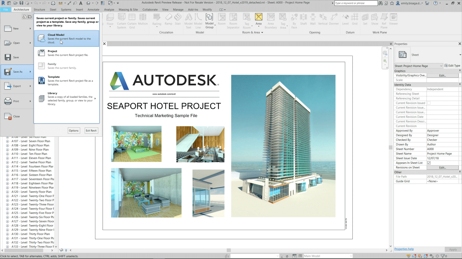
    1. Easily save non-workshared Revit files to the cloud

    Rather than uploading non-workshared files onto BIM 360, you can now save them directly to the cloud.  This will be really handy for smaller linked files that may not need to be workshared.

    2. Better collaboration with Civil 3D and topography

    With the release of 2019.1 you could Link topography from a Civil 3D drawing (that has been published) to your Revit project.  In 2019.2, they increased the functionality and you can now add building pads and sub-regions to that Linked Topography.  Keep in mind that you need Autodesk Desktop Connector installed to get access to that link through BIM 360.

    For more information on the release, visit the Revit Blog – Revit 2019.2 new features connect data, cloud, and customers.

    Ever wonder how new features make it into the program? Revit Idea’s Page  is an Autodesk forum where they capture feedback and requests from users.

    Civil 3D 2019 Update 2

    A new update for Civil 3D 2019 has just been released.  You can find it in the usual places; the Desktop App or your Autodesk Account.  Here is the ReadMe; note that AutoCAD 2019.1.2 must be installed prior to this new Civil 3D update.

    See this video outlining some of the new functionality.

    As always, updates contain fixes to known defects and some new functionality.  Here are the notable new features:

    • Transparent commands are now included in their own ribbon.
    • Transparent commands can now be accessed via the right click menu.
    • There is some new transparent command functionality with Alignment Station and Offset.  This in the name of efficiency and it’s an excellent addition.
    • Linear crossings in profile views.  This is, in this blogger’s opinion, is arguably revolutionary!  For many years users have requested the ability to display in profile where something crosses your alignment.  Another alignment, feature line, etc.  now we can.
    • UNC paths for projects.
    • Sample lines data shortcuts are “Vaultable”.
    • Property set data is supported in LadnXML.
    • Rail platform edge improvements.


    Infrastructure Road Show Series – Recap

    Recently the SolidCAD civil team conducted the first Infrastructure Road Show series across Western Canada!

    Our roadshow series was designed to uncover emerging technologies and new software, share best practices and industry trends and provide you with the best tips and tricks to streamline your workflow and finish your project faster.

    As those who attended know, there was a lot of information shown so feel free to download the Powerpoint files and view them at your own pace.

    Point Clouds

    Design Roundtrip

    Tips & Tricks

    Civil 3D 2019.1 Update

    Autodesk has released the first update for Civil 3D 2019. It is called the Civil 3D 2019.1 Update. As is the new norm, updates contain fixes and also feature enhancements. You can discover all of the details in the official Autodesk ReadMe; I’ve outlined some of the highlights below.

    Not everyone reads the readme before installing, so to avoid the likely error message that 2019.1 will not install…The AutoCAD 2019.1 Update is a prerequisite of the Civil 3D 2019.1 Update and must be applied prior to installing the update.

    New Features
    • Rail tools and content.
    • Rail alignment offsets and cant support.
    • Sample line groups can now be data referenced.
    • Multiple connection points for pipe structures.
    • Publish a surface to BIM 360 for consumption in Revit.
    Fixes
    • Data shortcut performance improvements.
    • Pipe rules are no longer automatically applied. (See this article.)
    • Vault fixes.
    • Many other defects have been addressed.