An update to the Desktop Connector as made available on August 11, 2020. Here is the relevant Autodesk document.
If you’re a Sheet Set user who also uses BIM 360, this update is for you. In addition to other resolved issues, the main feature in this update is that Sheet Set DST files are now recognized. When a DST file is uploaded via the Desktop Connector, any drawings contained therein and their references are all uploaded. When a DST is opened in AutoCAD, drawings will be synchronized locally.
Many users create PDF files from AutoCAD products as PDF seems to be the standard digital format. There are three issues you may run into and some settings to consider if you use Bluebeam Revu as well as AutoCAD.
Viewports
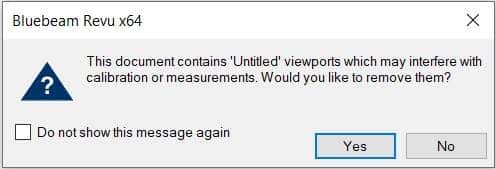
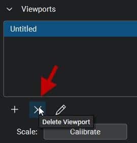
First, you may see this message when opening PDF files using Bluebeam Revu (not the free viewer) which were created from AutoCAD using Autodesk’s DWG to PDF print driver. These “viewports” are artifacts contained within the PDF file to which Bluebeam Revu alerts you when you open a file containing them. ALWAYS say yes to removing these artifacts. If you don’t, they will very likely affect the accuracy of any measurements you make in Revu. If you skip past this message without selecting Yes, the viewports can be removed from the PDF in Revu’s measurement panel.
Why do they exist in the first place? It seems to be an issue with Autodesk’s DWG to PDF.pc3 file. PDF’s created using Bluebeam’s PDF printer do not contain these anomalies. Here is an Autodesk discussion group thread discussing these viewports. Interestingly, it indicates that these viewports can cause an issue when measuring using Adobe Pro, but there appears not to be a solution there, where Revu does indeed catch the existence of them.
Searchable Text and SHX Fonts
The second issue is searchable text. Many AutoCAD users still use Autodesk SHX fonts. There are several reasons to avoid using SHX fonts; not the least of which is that when a PDF is created containing them, that text will not be searchable when opened in any PDF reader software. If you want your recipient to be able to search text, and you very likely should, do not use SHX fonts in AutoCAD. Use a True Type font, such as Arial instead. This is with one exception. With Bluebeam Revu, SHX text is in fact searchable, but you must enable “Search Markups”. More detail about this I the section below “Odd Markups”.
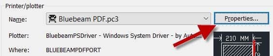
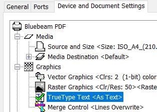
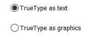
If you’re a Bluebeam Revu user with the CAD version or better, and you prefer to use its PDF print driver instead of Autodesk’s, there is an option to enable SHX fonts as outlined in this article. Better, do use a True Type font as mentioned above, but there is one more setting you must enable. A PC3 file must be created using the Bluebeam print driver and then this option set in the printer properties in AutoCAD. It defaults to TrueType as graphics and your text will not be searchable if it’s not changed.
Odd Markups in Revu
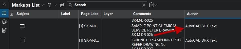
Lastly, using Bluebeam Revu (not the free viewer) to open a PDF created by AutoCAD using its DWG to PDF printer, you may see “markups” already contained in the PDF. There will be one markup for each text object in the file, indicated by the AutoCAD SHX Text author. That adds up to a lot of markups if it’s a file with many text objects. This can affect the performance of the file within Revu and they will definitely be in the way when creating normal markups. These markups are only required if you need to search SHX text; they cannot be deleted with Revu tools. They can be Flattenedin Revu prior to adding your own usual markups, or they can simply be filtered out if you don’t wish to see them. Don’t worry, the text in the PDF will not disappear. I do not have access to Adobe Pro to see if this is an issue there as well.
These “markups” are created when printing from AutoCAD using the DWG to PDF driver and it is an Autodesk feature. In AutoCAD, there is a variable named PDFSHX. Turned on, a value of 1, enables these “markups” in the PDF file which results in searchable text. Turning it off will result in no “markups” and non-searchable SHX text. Here is an Autodesk document outlining this feature. SHX text may or may not be searchable depending on the PDF reader in use. For example, the Bluebeam Revu free viewer cannot search SHX text, but the paid version can.
This issue does not occur with PDFs created in AutoCAD using Bluebeam’s printer driver.
It’s that time of year again folks; Autodesk has released their flagship product in AutoCAD 2021. Here is an excellent article explaining the new changes. Below are the features that are close to this BLOG writer’s heart.
Format
There is no format change this year. Excellent!
Enhanced Commands
Trim and Extend have new default behavior resulting in fewer clicks.
Revision clouds are now their own object. Including a new Arc Length property.
The Break At Point command can now be repeated resulting in fewer clicks.
Drawing version history comparison for files stored in cloud services such as OneDrive and DropBox.
The block palette now contains a Library for blocks stored in cloud services or other folders.
AutoLISP
A brand new AutoLISP development interface which uses Visual Studio Code with a LISP extension. Auto-complete functions and parentheses.
Plan production tools in Civil 3D are great for creating plan and profile sheets, but what about when the inevitable design changes come and you need to update your sheets? You either update them manually or recreate all new sheets. With CTC Software’s Sheet Generator, you can create plan and profile sheets that update after designs change, including refreshing of viewports, north arrows, matchlines, sheet names and numbers, sheet set data, and more. Sheet Generator provides better control on Profile Views, more flexible sheet management workflows, and easily dovetails with your company standards.
While Pipe Networks are a great toolset in Civil 3D, they fall short as a true design tool. With CTC Software, we can edit pipe runs through a design-oriented, dynamic interface. We can swap multiple parts, both pipes and structures, in plan or profile. We can also auto-populate properties across multiple parts at once, aiding in proper labeling or tabling.
Imagine a world where you could get high resolution background image maps to display and PRINT in AutoCAD.
Esri and Autodesk are working closer than ever and this alliance benefits all CAD and GIS users. Esri provides a free ArcGIS for AutoCAD plugin. This plugin allows vanilla AutoCAD users to access Esri maps. As mentioned, the beauty of these maps is that they also print/plot in AutoCAD.
This is the third in a three-part series of Fusion Lifecycle videos. In this video, we will focus on Change Management with a specific focus on Engineering Change Orders.
In the previous video, we saw that the Bill-of-Materials was automatically extracted and transferred to Fusion Lifecycle for additional analysis, modification, export and so on. At a future point in time, someone may recognize a problem with an item in the Bill of Materials and wants to initiate a change. In Fusion Lifecycle, they can log a Problem Report. The Problem Report flows through a structured workflow becoming an Engineering Change Request(ECR) and then an Engineering Change Order (ECO).
When the ECO is approved, Fusion Lifecycle pushes the information back to Vault, where the impacted assembly is changed to a Work-in-Progress state. Designers can then make the necessary design changes and Release the revised assembly.
Many of us use keyboard shorts and aliases to keep our eyes on the drawing area and keep our thoughts on our design. Searching for commands on the ribbon, especially if it’s buried in the pull-down portion, is probably not our favorite things to do. The right-click contextual shortcut menus are one of the key tools for keeping ribbon searching at bay.
Shortcut menus are great. They are fully customizable, and even out of the box they have some useful commands. What makes them even better are that each one of these can be selected with just a keystroke.
Let’s look at the two core shortcut menus: “Default Menu”, which pops up if no objects are selected, and “Edit Menu”, which pops up if at least one object is selected.
Default Menu:
R: Repeat
C: Clipboard
T: Cut
C: Copy
B: Copy with Base Point
P: Paste
K: Paste as Block
D: Paste to Original Coordinates
I: Isolate
I: Isolate Objects
H: Hide Objects
E: End Isolation
U: Undo
R: Redo
A: Pan
Z: Zoom (real-time)
Q: Quick Select
F: Find… (find/replace text)
O: Options
So, pan command can be run with a simple right click followed by pressing A. In the above list, Isolate and Pan are nice. The rest have decent keyboard shortcut or alias options already, but things get much more interesting with the edit shortcut menu. The Edit shortcut menu hotkeys are listed below (except for those already listed above):
Edit Menu:
E: Erase
M: Move
Y: Copy
L: Scale
O: Rotate
D: Draw Order
F: Bring to Front
B: Send to Back
A: Bring Above Objects
U: Send Under Objects
G: Group
G: Group
U: Ungroup
A: Add to Group
R: Remove from Group
D: Add Selected
T: Select Similar
A: Deselect All
S: Properties Palette
Basic editing commands like copy, rotate and move are made significantly made easier with the shortcut menu hotkeys. Draw order hotkeys are solid, as are Group hotkeys (if you use the group feature). Add Selected is amazing (draws a new object of the same type and as if match properties were applied afterwards), as are Select Similar and Properties Palette.
Best of all, whether you decide to throw more commands into the shortcut menu or not, you can manually add or edit the hotkey for each item. Let’s look at the Undo item in the “Default” shortcut menu in the CUI:
Note how there is an “&” character in the name of the item in the shortcut menu. That designates the letter that follows (U) as the keyboard hotkey for that item.
What this allows, essentially, is to open a second set of keyboard shortcuts that are accessed with the right mouse button.
I know there are still many drafters who prefer to use the right mouse button to repeat the last command rather than access the shortcut menu. There is nothing wrong with that. If you are a shortcut menu user, however, it gives you all sorts of hotkeys through the right mouse button so that you can keep your eyes on the drawing area and your mind on design. Consider giving shortcut menu hotkeys a try if you don’t use them already.
Have you ever saved and used Assembly Sets within the Intersection Wizard for saving your custom assemblies for future use? Have you ever had issues with them not appearing to work properly every time you use them? Have you ever wanted to share them with other team members?
This document will shed some light on why; and what you need to do to make them work every time.
Intersections
Civil 3D intersections are complex corridors containing many assemblies, regions, and baselines. Creating and editing them without the Intersection Wizard takes skill, time, and patience. There are up to 8 assemblies required for a typical intersection and creating them is also time-consuming and prone to errors. The image below shows a corridor which contains just one intersection, complete with all of the baselines, regions, and assemblies applied.
Assembly Set Basics
If you’re not familiar with them, Assembly Sets can be accessed and saved from within the Intersection Wizard when creating a new intersection or when Rebuilding Corridor Regions for an existing intersection. You simply create new assemblies or edit the ones that Civil 3D creates for you, and then export the set for use on future intersections, so you don’t have to recreate the assemblies every time.
The Assembly Set is saved as an XML file initially stored in its default folder…
C:\ProgramData\Autodesk\C3D 2020\enu\Assemblies\Metric
The Problem
There are technical support cases where the user has indeed exported an Assembly Set, but the proper assemblies do not appear after the set has been selected. In the image below, the custom set was selected where all the assemblies were renamed to MPK… As you can see, it appears as if an out of the box set was selected; no MPK assemblies are listed.
The Solution
There are 4 different scenarios where Assembly Sets are used. One for each of the two corridor types, selected within the intersection wizard…
One for a T intersection…
And one for a cross intersection.
If you open the Assembly Set XML file with your internet browser, you will see the 4 scenarios listed and the assemblies applied to each scenario. In the second image below, note the AssemblyName is set to MPK Primary…
When you save the Assembly Set, only the current corridor type is exported, only 1 of the 4 scenarios. The next time you use the Assembly Set, if that corridor is of a different type, your custom assemblies will not be applied since that corridor type has not been exported.
To ensure your custom assemblies are used in all 4 scenarios, you must go through the intersection wizard 4 times, one for each scenario and export the Assembly Set for each of them.
Create a cross intersection and specify All Crowns Maintained.
Create a cross intersection and specify Primary Crown Maintained.
Create a T intersection and specify All Crowns Maintained.
Create a T intersection and specify Primary Crown Maintained.
Select the same XML file each time, the exported scenario will overwrite only the applicable section of the selected XML file.