• Civil 3D Assemblies: Tool Palette or Block Library?

    Civil 3D Assemblies: Tool Palette or Block Library?

    Civil 3D comes shipped with pre-configured assemblies that may or nay not fit your needs.  We created another BLOG post here to show how to create your own and share them with others in your team.  There is another way…read on.

    The Cole’s notes are:
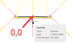
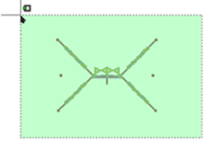
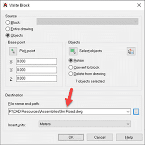
    • Make a new drawing.
    • Create your assembly in this new drawing placed at 0,0.
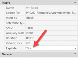
    • Insert that drawing into your design and explode the resulting block.

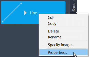
    In the linked article above, we suggested creating a tool palette.  This works well for blocks so they may be placed on the correct layers.  For assemblies, since this block will be exploded, this is not a requirement.  Might there be an easier way?  There is.  You see, tool palettes require a little maintenance.  The trick below does not.

    AutoCAD’s Block Library

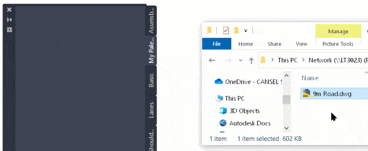
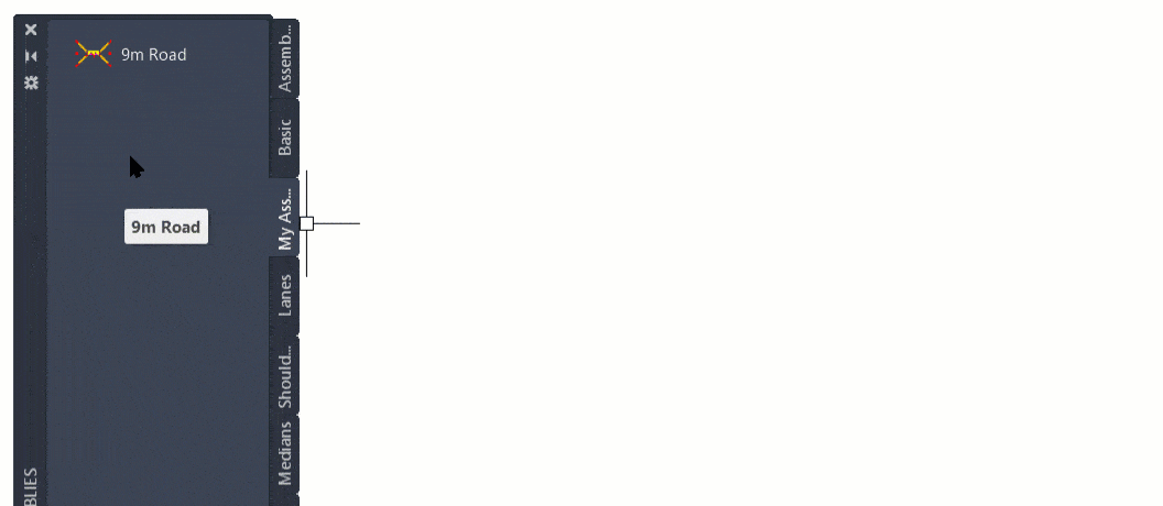
    In Civil 3D 2022 or later, open the new block palette introduced in version 2020.  The option I’m about to illustrate is not available with 2020 or 2021.  You will see two things: a Library tab (red) and a button to select a folder (blue).  Clicking the folder button will prompt you to select a folder containing drawings.  If each of those drawings is an individual assembly, your job is done.  Drag and drop one of those into your drawing and ensure it is exploded.  You’ve just inserted an assembly.

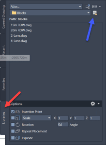
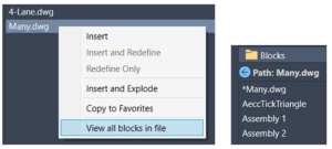
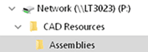
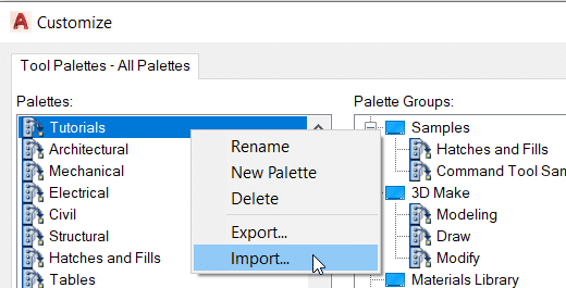
    No maintenance is required.  Just save a new drawing with a new assembly into that folder and the next time AutoCAD is started, you’ll see the new content.  If you prefer to have all assembly blocks defined in a single drawing, that’s fine too, simply right click the drawing and choose…

    Enjoy!

    AutoCAD 2023: New Release

    AutoCAD 2023: New Release

    It’s that time of year; Autodesk has just released the 2023 version of their flagship drafting application, AutoCAD.  Read on to discover some of the new features.

    Click to peruse Autodesk documentation.

    Compatibility

    Likely one of the most common questions is about compatibility.  AutoCAD 2023 remains in the 2018 format.  There is no need to save files to previous versions unless your recipient is using 2017 or earlier.

    Markups

    I’m intrigued by this feature more than any other this year. PDF markups are ubiquitous in our industry, but there were few tools to help manage them.

    In AutoCAD 2023, PDF markups can be overlaid and displayed more easily, and they can then be imported as a trace layer and converted to AutoCAD objects. Markup assist will use text recognition to add AutoCAD text, multileaders, and revision clouds from the PDF markup. Image file formats are also supported if the PDF is scanned and marked with coloured pens.

    Insights

    Machine learning provides tips and tricks when and where you need them.  AutoCAD generates macro insights based on your unique command usage.

    LISP

    LISP apps can be loaded and run within the AutoCAD web app.

    General

    The command line is visible within each active floating window.

    Count has been updated to enable easier navigation and selection.

    The Sheet Set Manager has been given a performance boost and has a new interface in Autodesk Docs.

    ANNOSCALEZOOM controls mouse zooming in paper space.

    MTEXT objects can be converted to MultiLeaders.

    TRACE is now available on AutoCAD desktop, not just in the web app. You can contribute to other users’ traces.

    2D Graphics performance has been enhanced. Zoom and pan performance has been increased up to 50 times with many true type text objects, long polylines, and solid hatches. 

    The new TRAVERSALTHREAD system variable controls this.

    A new 3D graphics system (GSF) has been introduced and it promised to increase performance.  GSFENABLE is the new variable that controls this. It is ON by default. To experience the benefits of this, use the visual styles named Shaded or Shaded with Edges.  FASTSHADEMODE is a new variable that controls this behaviour.

    CUTBASE is a new command (Cut with base point found in the right-click menu) to allow the selection of a base point when cutting objects from a drawing.

    Add a new vertex to the end of a polyline with the extend vertex option

    Civil 3D: Sharing Assemblies

    Civil 3D: Sharing Assemblies

    So, you’re the technical team lead for your Civil Engineering firm, and you need to share amongst your team some Civil 3D Assemblies.
    You know how to create an AutoCAD tool palette, and you know that this is the best place to share assemblies – but you’ve tried, and it’s not working.

    If you’d like to learn how this is done read on.
    Palettes can be exported and then imported onto users’ machines, but when an assembly is edited, the creator must export again and then all the users must again import. This is not efficient.

    The Hard Way

    The method that Civil 3D uses to store assemblies on a palette works well, but to set it up is a bit of a bear.  Open this document to see the full details.  Here is a summary:

    • When an assembly is dragged to a tool palette a new DWG is created on your system. For my system this is:
      C:\ProgramData\Autodesk\C3D 2022\enu\Assemblies\Metric
    • You can create a tool palette with custom assemblies, sure, but you need to make these drawings available to your users. Usually, this means copying them to a network shared folder.
    • Even when you make them available, the DWG path must be defined in an ATC file that defines the palette, This is XML programming language and it can be difficult to find and disastrous if an error is made.

    The Easy Way

    I won’t say this is “The Best” method, but I believe it to be the easiest, quickest, and most foolproof method; and it’s the one I choose to use at this time.

    I won’t go into detail about how to perform each of these steps; it is assumed you know the technique. The short answer is that each assembly will reside in its own DWG file and that file will be stored in the shared network folder. That file will be a block in the tool palette.

    Open a drawing that conforms to your Civil 3D standards. Possibly one that already contains your desired assembly. 

    1. If the assembly has yet to be created, create it. 
    2. Ensure it is on the desired layer. Assign the desired code set style to it. Move it from its insertion point to 0,0. If this last step is skipped, the assembly will not be inserted properly later.


    3. Save the drawing to your shared network folder.


    4. WBLOCK and select the assembly and subassemblies together.  Ensure the insertion coordinates are 0,0,0 and provide the file name.  Click OK to create the drawing.


    5. Create a new tool palette or set current the destination palette for your new assemblies.  Drag the newly created drawing into the palette.

    6. To use the new assembly, drag it from the palette into a new drawing.  This will be a block, however.  It will need to be exploded once.

    7. You may suggest turning on the Explode option in the tool to avoid the explode step.  Indeed, I thought of that as well.  Problem is, this is what you get!


    That’s it.  Once the assemblies have been created, it takes about 45 seconds per assembly to add to the palette.  If edits are required, simply open the appropriate DWG, make the edits, and save.


    Civil 3D Double Click Customization

    Is there a Civil 3D object that you would like to double click and run a specific command?  if so, read on.  (This works for AutoCAD commands too.)

    Try double-clicking an Alignment.  The AutoCAD properties palette appears.  What if we want the Alignment Properties dialog instead?  Or if you want the Feature Line Quick Elevation Edit tool to be run when you double click a Feature Line.

    Edits to the CUI file are required.  Please do yourself a favor and create a partial CUI file and make these edits in there.  And while you’re at it, save this file somewhere like My Documents.

    1.  Determine the object name.  Run the LIST command and select the object.  The object name will be shown.  Mine is AECC_ALIGNMENT.
    2. Run the CUI command.  The double-click assignments are stored in the CUI file.
    3. Right-click to add a new double-click action.  Name it something like Alignment Properties

    5. On the right half of the CUI editor, enter the appropriate object name.

    6. Find the appropriate command in the bottom-left window.  In this case, Alignment Properties.  Drag it onto your new double-click action.

    7. Close the CUI editor.

    8. You’re done!  Double click the object and the command will be run.

    Create Your Own AutoCAD Tutorial Library

    Are you or do you have a staff member in your office who likes to create tutorial content?  Or maybe you simply have some web links to which you’d like to regularly refer.  Maybe you’d like to share these tutorials with the rest of your AutoCAD team.  Sure you can tell them where the videos, documents, or web links are, but the users must open them outside of the AutoCAD environment.

    What if the users could access this content right within AutoCAD?  The closer the help is to the user, the better, I always say.  Consider creating a custom tool palette containing buttons to open these tutorials, and sharing it with the users.

    I’ll go on the assumption you already know how to create and share a tool palette.  I’ll show you how to create tools that link to files or web links.

    Create the Tool

    Drag a line or a text object to your new tool palette then edit its properties.

    Web Link

    Edit 5 properties:

    • Name.
    • Description.
    • Specify Image.
    • Turn off the flyout option
    • Edit the Command String.  Enter this information ^C^C_browser https://WebLink  Paste the link after browser.

    File

    The only difference between this tool and the web link is the Command string which uses a little LISP code.  Enter the path to your file after findfile, within the quotes.  DO NOT use back slashes, only forward slashes.

    • ^C^C (startapp “explorer.exe” (findfile “C:/temp/1.docx”))

    That’s it.  Make it easy for your users to get the help they need!


    Infraworks 2021.2 Update

    Autodesk has released the next update for Civil 3D 2021.  Find the release notes here.  Here are some highlights:

    • Add decorations to component roads imported from Civil 3D.
    • Modify lane markings for component roads.  No lane marking shadow issues.
    • Various improvements to Civil Structures.
    • A new Home screen including Recent and BIM 360 tabs.
    • Select a coordinate system during model creation using the Model Builder.
    • Add a point cloud in LAS or LAZ format without first saving an RCP file.

    Civil 3D 2021.2 Update

    Autodesk has released the next update for Civil 3D 2021.  Find the release notes here.  Here are some highlights:

    New ArcGIS workflows:

    • Refresh data sources.
    • Import raster data as an image, or as surface data.

    New Pressure Network Workflows

    • Create parts lists from multiple materials.
    • Override pipe run offsets for specific station ranges.
    • Use expressions in profile band labels.

    Civil 3D Pressure Pipes

    Civil 3D 2021.1 introduced several new features including a new compass when creating a pipe run.  This is excellent news, but depending on your modeling requirements, it can cause an issue if you leave in a new setting.

    In the examples below, the parts list has no bends, and they are not needed for this design.  The pipe runs as required to be drawn like a polyline.  While working with a customer, I ran into this issue, but I could not find the solution, and surprisingly, neither could Autodesk.  Thanks to my esteemed colleague, Colin Gaudet for discovering what turns out to be a very simple solution.

    2021.0

    This is the behavior from 2021.0 and it is the expected behavior.


    2021.1

    This is the behavior after installing 2021.1.  The compass indicates that there are no bends and it will not allow any angle to be drawn, only a straight line.


    The Setting

    There is a new setting to allow pipe runs to be “snapped” to known bend angles.  Turn off the new setting to return to the expected behavior when there are no bends.  The compass remains, but it now allows any angle to be drawn.

    Program Validation with Spreadsheet Link and Room Family Manager – Part 2

    Posted CTC BIM Project Suite White Paper Library –  CTC Software

    End Result

    When the workflow is developed and implemented, the entire special program can be added to the Revit project in a matter of minutes. Design area versus actual modeled area can be compared and analyzed ondemand. Content for each space can be placed per room specifications, whether the families are loaded or not. If layouts change, or if equipment needs to be replaced, the process ca be completed in minutes instead of hours. Any user can utilize this workflow to import the program requirements into their projects, update the models, import the content and finish the design. This process speeds up a task that takes lots of time and removes lots of potential user error.

    Savings/Benefits

    Time savings can be applied to several different aspects of the project. Planners can continue to use Excel to generate the lists needed for the room import, pulling from defined lists of data instead of guessing or looking up the data themselves. They never have to open Revit if they do not want to. The manual, error prone process of reading data from one source, and entering it into another source can be eliminated. This allows the designers and Revit users to focus more on the actual design and layout of the project more than focusing on the data they have been retyping.

    Conclusion Spreadsheet Link and Room Family Manager from the CTC BIM Project Suite can help import the building program and assist with data comparison and with design changes. The process above is intended to be the starting point of a template that can be expanded upon to include additional information, making the process fit the needs of the project and the team. If taken a few steps further, most of the data and content needed can be managed with just a couple of Excel files. Both Revit users and non-Revit users can take part in this process, and still have their designs imprinted on the project.

    Program Validation with Spreadsheet Link and Room Family Manager – Part 1

    Posted from CTC BIM Project Suite White Paper Library –  CTC Software

    Issue

    When working on medium to large buildings, how are you managing your program requirements? How are you checking the intended design area? In what way do you capture the number of required elements in a specific space? How can you assist the designer with room layouts and making sure the required equipment is used in the correct space? What happens when the design or the requirements change? Is there a way to compare data and assist with these changes? This session will demonstrate a process that will answer these questions, using tools you may already have at your fingertips: Spreadsheet Link and Room Family Manager. These tools can be powerful assets when establishing building programs.

    Typical Workflow In manual workflows, many architectural firms will use an Excel® spreadsheet containing all the special requirements needed for the building. Occasionally, some firms will have a process to export the data from Revit® and linked directly into this spreadsheet. Most firms will export the room data from their Revit design models, and manually enter the data in their spreadsheets. But what happens on the return side? How this data gets back into Revit almost always is another manual process. There are a handful of Issue When working on medium to large buildings, how are you managing your program requirements? How are you checking the intended design area? In what way do you capture the number of required elements in a specific space? How can you assist the designer with room layouts and making sure the required equipment is used in the correct space? What happens when the design or the requirements change? Is there a way to compare data and assist with these changes? This session will demonstrate a process that will answer these questions, using tools you may already have at your fingertips: Spreadsheet Link and Room Family Manager. These tools can be powerful assets when establishing building programs. Dynamo workflows and paid Revit plugins that are meant for this process specifically, but they either take dedicated professionals to create and maintain, or they cost a lot of money to purchase. Unfortunately, these tools are not commonly used. Then what about the content required to be placed in each space? Often, a designer is reading from the spreadsheet, browsing through their Revit library and manually placing the content into their projects. If the design changes, or the requirements change, it all becomes a manual process, updating both the spreadsheets in Excel, and updating the models in Revit.

    Solution This entire workflow can be simplified by using a couple of tools that many firms already have: Spreadsheet Link and Room Family Manager, both from the CTC BIM Project Suite. A template can be created for the type of project and spaces that are being used, to assist with populating special data obtained in the building program. This data can be pushed into the Revit models, and a back-and-forth design process can begin. For the content to be placed within the rooms, Room Family Manager will help with defining the list of equipment required by each space, and help with populating each space with the defined list, and again another back-and-forth design process can begin.

    Subscribe to SolidCHAT blog for part 2.