• BING Images Won’t Appear

    Have you ever turned on background BING imagery inside AutoCAD products only to find they don’t appear?  There could be a few reasons for this:

    • No Geolocation or coordinate system is set.
    • You’re not logged in with your Autodesk account.
    • You’re zoomed into an area compatible with the geolocation you’ve chose.

    These two are the pre-requisites for using images from BING, but there is one more which has many of my customers stumped.  Have you ever seen this message?  You almost certainly have.

    If you choose Yes, then you will see your images.  If you choose No, you won’t.  If you check that little button on the bottom left, you’ll never see this message again.  Good, right?  Well, if you chose Yes, then yes.  If you chose No, well…you’ll never receive this message again and you’ll never see images!

    There is a saviour, however.  There are other message like this in AutoCAD.  Toggles that prevent that box from appearing in the future.  These are called “Hidden Messages” and they can be turned back on by opening AutoCAD’s Options dialog box [OPTIONS].  Then opening the hidden message settings in the System tab.


    I hope you can use this to avoid any unnecessary frustration in your day.

    Civil 3D Assembly Sets

    Have you ever saved and used Assembly Sets within the Intersection Wizard for saving your custom assemblies for future use?  Have you ever had issues with them not appearing to work properly every time you use them?  Have you ever wanted to share them with other team members?

    This document will shed some light on why; and what you need to do to make them work every time.

    Intersections

    Civil 3D intersections are complex corridors containing many assemblies, regions, and baselines.  Creating and editing them without the Intersection Wizard takes skill, time, and patience.  There are up to 8 assemblies required for a typical intersection and creating them is also time-consuming and prone to errors.  The image below shows a corridor which contains just one intersection, complete with all of the baselines, regions, and assemblies applied.

    Assembly Set Basics

    If you’re not familiar with them, Assembly Sets can be accessed and saved from within the Intersection Wizard when creating a new intersection or when Rebuilding Corridor Regions for an existing intersection.  You simply create new assemblies or edit the ones that Civil 3D creates for you, and then export the set for use on future intersections, so you don’t have to recreate the assemblies every time.

    The Assembly Set is saved as an XML file initially stored in its default folder…
    C:\ProgramData\Autodesk\C3D 2020\enu\Assemblies\Metric

    The Problem

    There are technical support cases where the user has indeed exported an Assembly Set, but the proper assemblies do not appear after the set has been selected.  In the image below, the custom set was selected where all the assemblies were renamed to MPK…  As you can see, it appears as if an out of the box set was selected; no MPK assemblies are listed.

    The Solution

    There are 4 different scenarios where Assembly Sets are used.  One for each of the two corridor types, selected within the intersection wizard…

    One for a T intersection…

    And one for a cross intersection.

    If you open the Assembly Set XML file with your internet browser, you will see the 4 scenarios listed and the assemblies applied to each scenario.  In the second image below, note the AssemblyName is set to MPK Primary…


    When you save the Assembly Set, only the current corridor type is exported, only 1 of the 4 scenarios.  The next time you use the Assembly Set, if that corridor is of a different type, your custom assemblies will not be applied since that corridor type has not been exported.

    To ensure your custom assemblies are used in all 4 scenarios, you must go through the intersection wizard 4 times, one for each scenario and export the Assembly Set for each of them.

    • Create a cross intersection and specify All Crowns Maintained.
    • Create a cross intersection and specify Primary Crown Maintained.
    • Create a T intersection and specify All Crowns Maintained.
    • Create a T intersection and specify Primary Crown Maintained.

    Select the same XML file each time, the exported scenario will overwrite only the applicable section of the selected XML file.

    Civil 3D Viewports

    A little tip today.  Have you ever zoomed out within a profile viewport and your surfaces and alignments are not there?  The two viewports shown below are nearly identical except the one on the bottom doesn’t display any Civil 3D plan objects, such as the surface and alignment.  Why is this?  No, layers are not frozen or off in the lower viewport.

    Civil 3D has its Plan Production feature which automates the creation of Paper Space layouts, typically for plan and profile construction drawings.  The way it has been implemented is that your drawing template (DWT) will contain a sample paper space layout containing pre-configured viewports.  And those viewports are required to have set a specific property called Viewport Type.

    In the image above, the top viewport is set to Plan and the bottom is set to Profile.  When the viewport type is set to Profile, Civil 3D plan objects such as surfaces, alignments, and corridors are not displayed.  This is presumably to conserve performance, but if you’re unaware of this feature, it can be confusing.

    Workaround: Civil 3D XREF Structures Do Not Resize

    My friend and customer, Ben Cartmell from Koers & Associates in Parksville, has brought to my attention a method, of which you may not be aware, for working around a limitation within Civil 3D.

    The limitation is when a drawing containing Civil 3D structures is XREF’d.  The image below shows two viewports in paper space with pipes and structures that have been XREF’d in model space.  The structures are annotative and they should be the same size within the viewports, but they are not.

    There is an easy workaround for this problem.  The file being XREF’d in the example above was saved in model space.

    • Open the file.
    • Switch to paper space.
    • Save.

    Reload the XREF and those structures now appear the same size in paper space.

    Feel free to experiment by downloading these two drawing files.

    4 New Features Architects should know Revit 2019.2

    Autodesk’s release of 2019.2 included some interesting features that Architects should be aware of.  There were a couple minor improvements to the program itself, but it seems like a larger effort is being placed on improving the functionality of Revit alongside BIM 360.

    Day to Day improvements: 

    1. Zoom functionality in schedule views.

    This is pretty handy for large schedules or if you are using a hard to read font style.

    How to Zoom in/out for schedules:

    CTRL +  = Zoom in
    CTRL – = Zoom Out
    CTRL 0 = Zoom Reset

    Alternatively, you can hold down CTRL and use your mouse wheel to zoom in and out.

    2. Removed “Element is too small on screen” warning

    Gone are the days of having to move something far away so you can move it to the right spot just to avoid this warning.

    If you are working with BIM 360:

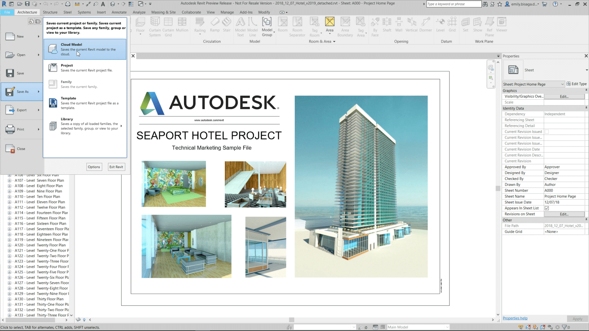
    1. Easily save non-workshared Revit files to the cloud

    Rather than uploading non-workshared files onto BIM 360, you can now save them directly to the cloud.  This will be really handy for smaller linked files that may not need to be workshared.

    2. Better collaboration with Civil 3D and topography

    With the release of 2019.1 you could Link topography from a Civil 3D drawing (that has been published) to your Revit project.  In 2019.2, they increased the functionality and you can now add building pads and sub-regions to that Linked Topography.  Keep in mind that you need Autodesk Desktop Connector installed to get access to that link through BIM 360.

    For more information on the release, visit the Revit Blog – Revit 2019.2 new features connect data, cloud, and customers.

    Ever wonder how new features make it into the program? Revit Idea’s Page  is an Autodesk forum where they capture feedback and requests from users.

    Ministry of Public Works – Government of Bermuda

    Success Stories

    Ministry of Public Works – Government of Bermuda

    The Ministry of Public Works is responsible for maintaining Bermuda’s critical assets and providing essential services. The Ministry manages and maintains public lands, buildings, highways, roads, water supplies and parks, provides essential services such as waste collection, sewage, land title and registration and land valuation.

    Project Profile

    In Bermuda, the Works and Engineering/Estates departments within the Ministry of Public Work, Government of Bermuda upgraded from Civil 3D 2011 to 2018 overnight. This sudden transition required their 8-person team to get up to speed in record time. Their training needs ranged from basic to advanced, and they also wanted to optimize data interchange between surveyors and the team.

    To learn more about other SolidCAD Customer Success Stories featured on the Autodesk Partner Finder, click here.

    Testimonial

    Because we are a branch of government, we needed to get three estimates for the work required. We reached out to multiple service providers in the U.S. and Canada. SolidCAD was incredibly responsive. They provided an intricately detailed proposal, and their prices were competitive. This was a remarkable engagement from start to finish, and the onsite trainer relayed his knowledge expertly.

    - Carolina Drew, Highway Design Engineer, MIHE

    Similar Projects

    Énergir

    Énergir, Québec's leading natural gas distributor, collaborated with SolidCAD to transition from MicroStation DGN to AutoCAD DWG, enhancing data accuracy, field safety, and interdepartmental collaboration.[...]

    Procepack

    PROCEPACK is a firm specializing in the purchase and sale of packaging and process equipment. They serve customers from a wide range of industries from food and cosmetics to pharmaceuticals. They leverage their vast and…

    Société de Transport de Montréal (STM)

    Public transportation – buses, trains, subways, and more – have a wide range of complex assets that are both mobile and stationary. Upgrades, expansions, and new assets become intricate engineering projects involving a broad array of[...]

    Civil 3D 2019 Update 2

    A new update for Civil 3D 2019 has just been released.  You can find it in the usual places; the Desktop App or your Autodesk Account.  Here is the ReadMe; note that AutoCAD 2019.1.2 must be installed prior to this new Civil 3D update.

    See this video outlining some of the new functionality.

    As always, updates contain fixes to known defects and some new functionality.  Here are the notable new features:

    • Transparent commands are now included in their own ribbon.
    • Transparent commands can now be accessed via the right click menu.
    • There is some new transparent command functionality with Alignment Station and Offset.  This in the name of efficiency and it’s an excellent addition.
    • Linear crossings in profile views.  This is, in this blogger’s opinion, is arguably revolutionary!  For many years users have requested the ability to display in profile where something crosses your alignment.  Another alignment, feature line, etc.  now we can.
    • UNC paths for projects.
    • Sample lines data shortcuts are “Vaultable”.
    • Property set data is supported in LadnXML.
    • Rail platform edge improvements.


    Infrastructure Road Show Series – Recap

    Recently the SolidCAD civil team conducted the first Infrastructure Road Show series across Western Canada!

    Our roadshow series was designed to uncover emerging technologies and new software, share best practices and industry trends and provide you with the best tips and tricks to streamline your workflow and finish your project faster.

    As those who attended know, there was a lot of information shown so feel free to download the Powerpoint files and view them at your own pace.

    Point Clouds

    Design Roundtrip

    Tips & Tricks

    Civil 3D 2019.1 Update

    Autodesk has released the first update for Civil 3D 2019. It is called the Civil 3D 2019.1 Update. As is the new norm, updates contain fixes and also feature enhancements. You can discover all of the details in the official Autodesk ReadMe; I’ve outlined some of the highlights below.

    Not everyone reads the readme before installing, so to avoid the likely error message that 2019.1 will not install…The AutoCAD 2019.1 Update is a prerequisite of the Civil 3D 2019.1 Update and must be applied prior to installing the update.

    New Features
    • Rail tools and content.
    • Rail alignment offsets and cant support.
    • Sample line groups can now be data referenced.
    • Multiple connection points for pipe structures.
    • Publish a surface to BIM 360 for consumption in Revit.
    Fixes
    • Data shortcut performance improvements.
    • Pipe rules are no longer automatically applied. (See this article.)
    • Vault fixes.
    • Many other defects have been addressed.