Do you use more than one CTB file when printing in AutoCAD? More than 10? 40? What if I said you really only need 1, the Monchrome.ctb file? Read on to find out how…
If you already understand CTB files, feel free to scroll down to the heading “Do This Instead”.
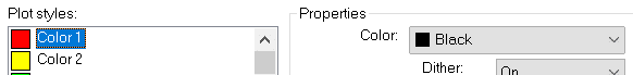
Let’s look at what we have to work with:
1.AutoCAD users use various colours.
2.Typically, the colours used are chosen from this 256-colour “Index” palette.
3.Those colours on the screen don’t always print that colour.
4.Linework need to print to varying widths.
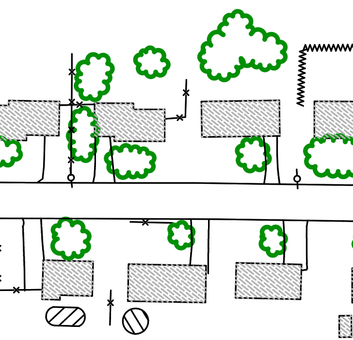
On-Screen:
Printed:
CTB files are the intermediary between the drawing on screen and the final printed product. If one is not used, what you see on screen is what is in the print. They are used to transform what is seen on screen to what is displayed in the print.
Many AutoCAD users rely on several CTB files to print documents to various regulatory standards. Here is why…
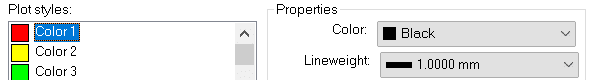
The City of SolidCAD requires a sanitary sewer layer to be red on screen but print black and thick (1mm).
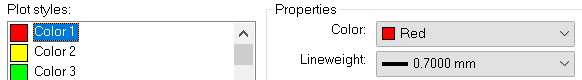
The District of Cansel requires that same sanitary layer to be red on screen but print red and not so thick (0.7mm).
42 other standards exist and a unique CTB file is required for each of them.
Here is the SolidCAD CTB file:
Here is the Cansel CTB file:
THESE ARE NOT REQUIRED!
Yes, that was a little tongue-in-cheek. Sometimes you’re sent a file and you just need to print and use the available CTB. But if you have the time, inclination, and desire to make things a little easier on yourself, understand it’s possible.
Do This Instead
The solution here is actually very simple. Follow these steps.
1.Set the line weight properly for the layer based on the regulatory body standard.
2.Use the out of the box monochrome.ctb file. This file prints all 256 Index colours in black.
How to print hat sanitary layer in red when the CTB file prints all colours black, you ask? Well, I didn’t say the CTB prints all colours black, just the 256 Index colours.
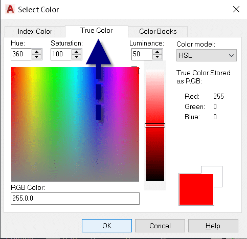
3.When colour is required set the layer colour, not to one of the 256 Index colours, but to one of the 16.7 million True Colours.
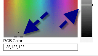
4.You need to print a grey shade? Again, choose a True Colour; just choose a colour at the very bottom. Use the slider on the right to control the shade.
You see, the CTB file does not control the output of True Colours, only the 256 Index colours.
Autodesk has released the latest version of their Civil Engineering package, Civil 3D 2022, and its partner in crime, Infraworks. Click to peruse the Autodesk Documentation. Recap 2022 has also been given some new features. Read on for some notable features.
Civil 3D
Grading Optimization: Takes the parameters that you have specified and generates, very quickly, an optimal grading solution. After installing Civil 3D 2022, you’ll find sample files in the folder C:\Program Files\Autodesk\Grading Optimization 2022\samples.
Connected Alignments: Supports complex curve groups, offsets from parent alignments, curves larger than 180-degrees, and calculates the cross fall of the associated profiles.
Project Explorer: Pressure networks are now supported. Multiple languages are now supported.
Infraworks
Road Decorations: Allows users to add decorations to component roads or linked corridors from Civil 3D. The InfraWorks model will display the features more quickly compared to previous releases.
Decoration Library: Now users can create more realistic landscape environments to add to the model context.
Bridge: Provides for the definition of full-span complex parametric 3D bridge girders.
Model Builder: Enhanced with a new and streamlined interface to provide a more consistent experience and improve usability.
Recap
Scan to Mesh: Select all or a portion of a point cloud in ReCap Pro 2022 and have it create a low, medium, or high-quality mesh. This was included in a previous version as beta software, but it was removed. It is back!
Label Genie, with it’s recent debut, changed how we do Civil 3D sheet annotation. Allowing automated insertion of labels across multiple drawings and layouts at once, Label Genie turns hours of work into minutes. The latest release will feature labeling in Profile and Section Views, and add many new label types, such as dimensions, blocks, pipe and pressure networks. Additional anchor objects will be included and new data sources will be available, such as block attributes, property sets, objects data, and more.
In this mini video series: Part 3, our Technical Consultant Infr/GIS – Colin Gaudet will showcase how you can automate labeling in Profile and Section Views, benefit from even more label types and anchor objects than before, and more.
For full information on CTC tools for Civil 3D click here
Auto Grader is a game-changer in Civil 3D site grading. Through dynamically linked feature line sets, users can create grading families for parking lots, ponds, subdivisions, and more. The latest release features a “template-based” grading method, allowing automatic insertion of a user-defined set of feature lines, such as a building pad, along defined baselines, such as a roadway. Other enhancements include more detailed surface targeting, automatic surface boundaries, better family preview controls, and other user-friendly features.
In this mini video series: Part 2, our Technical Consultant Infr/GIS – Colin Gaudet will showcase detailed surface targeting, automatic surface boundaries, better family preview controls, and other user-friendly features in the video below.
For full information on CTC tools for Civil 3D click here
Earthwork volume calculations can be a complex task in Civil 3D, especially with variable depth subgrades found in many site projects. With the CTC Earthwork Processor in the CIM Project Suite, this work is done for you. Subgrade and stripping surfaces are created based on intuitive inputs, then results can be automatically labeled, tabled, hatched or exported to a spreadsheet.
In this mini video series: Part 1, our Technical Consultant Infr/GIS – Colin Gaudet will give you a quick overview of Earthwork Processor from CTC CIM Project Suite and cover some of the main features and capabilities.
For full information on CTC tools for Civil 3D click here
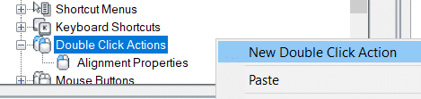
Is there a Civil 3D object that you would like to double click and run a specific command? if so, read on. (This works for AutoCAD commands too.)
Try double-clicking an Alignment. The AutoCAD properties palette appears. What if we want the Alignment Properties dialog instead? Or if you want the Feature Line Quick Elevation Edit tool to be run when you double click a Feature Line.
Edits to the CUI file are required. Please do yourself a favor and create a partial CUI file and make these edits in there. And while you’re at it, save this file somewhere like My Documents.
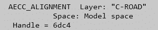
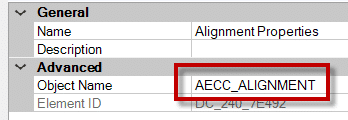
Determine the object name. Run the LIST command and select the object. The object name will be shown. Mine is AECC_ALIGNMENT.
Run the CUI command. The double-click assignments are stored in the CUI file.
Right-click to add a new double-click action. Name it something like Alignment Properties
5. On the right half of the CUI editor, enter the appropriate object name.
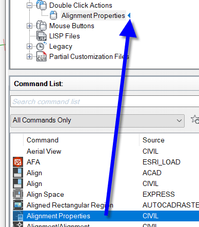
6. Find the appropriate command in the bottom-left window. In this case, Alignment Properties. Drag it onto your new double-click action.
7. Close the CUI editor.
8. You’re done! Double click the object and the command will be run.
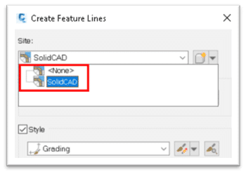
Which option do you choose when creating a feature line? In my early days of learning Civil 3D I was given an analogy of buckets. That any of the objects in a site, “Bucket”, could not interact with other objects, this was the purpose of sites.
This analogy was half-true and only the tip of the iceberg.
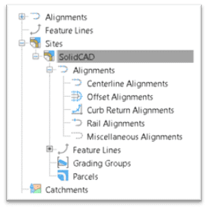
For starters, sites can only house certain objects, and only parcels and grading groups are confined within sites.
Alignments and feature lines have the option.
The limited interaction between these “Buckets” only limits the interaction of the objects in a site from communicating with the objects in another site. That’s why we can choose to restrict feature lines and alignments.
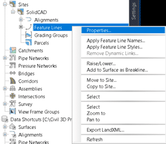
However, when feature lines are contained in a site, we have additional control over their interactions with one another.
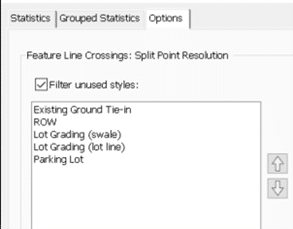
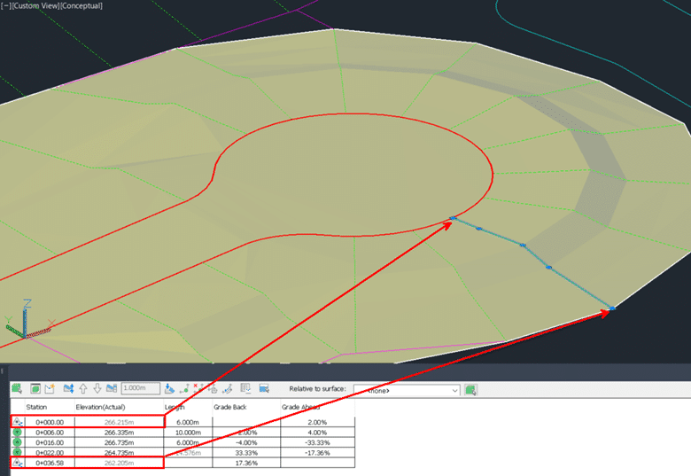
This is called Split Point Resolution and it allows us to set which feature lines govern at a crossing. Assigning styles to feature lines, we can set which styles are the most important for the design.
I use this for lot grading to manage a variety of constraints and to make sure that right of way and existing elevations are respected.
Using the split point resolution while grading this cul-de-sac, it ensures the lot lines obey the right of way and the existing tie in points.
This technique can be used in many other grading scenarios like drops in a curb or pond access paths.
It is a powerful concept that not many designers have embraced yet.
And if that isn’t powerful enough for you, consider using CTC Software’s Auto Grader to automate the rest of your grading! This tool dovetails beautifully with the native split point resolution for feature lines in sites.
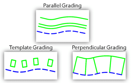
Auto Grader has 3 different types of “Grading Families” that can be used to tackle almost any grading project.
Parallel Grading allows mass dynamic stepped offsets from one or multiple baseline feature lines. Offering flexible grading for project areas such as curbs or ponds
Perpendicular Grading allows mass insertion of elevation points/grade breaks across feature lines connecting to a baseline feature line. Offering automated grading solutions for lots in a subdivision or drop curbs.
Template Grading is the newest addition to this tool allowing incredibly flexible 3D insertion control over template feature lines. Allowing you to establish grades from baseline feature lines and associate relative grades to the inserted template. This offers unparalleled flexibility for operations such as building envelope insertion.
Hopefully, this challenges you to find even more efficiencies in your use of feature lines.
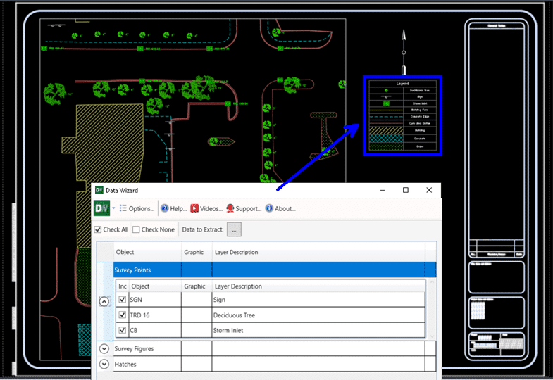
Flexible, Customized Legends and QTOs with CTC’s Data Wizard.
How do you tackle quantity takeoffs in your projects? Do you use Civil 3D’s QTO Manager? Do you scale on paper or PDF’s?
Between the inaccuracy of paper and PDF calculations, and the tedious setup and inflexibility of the MTO Manager, we don’t have a great solution for quantities of what’s in our projects.
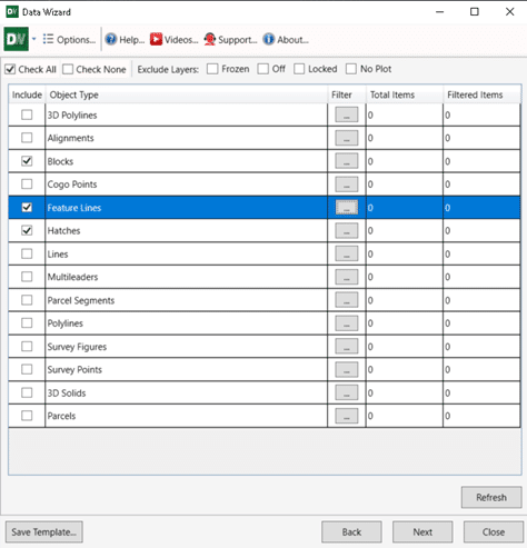
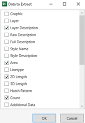
Data Wizard can make this cumbersome task a lot more efficient and accurate. This tool searches your drawing for Civil 3D & ACAD point, line, and area type objects then tabulates them all for you.
This is a very versatile tool, and once objects are selected and filtered, we can choose specific data to extract. In the case of QTO, a layer description can be used to label the item. Then areas, lengths, and counts can be tabulated for each respective item.
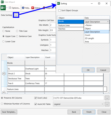
We can then sort and prep this data for AutoCAD Table insertion, or export to Excel. Data Wizard allows you to customize what you are looking for every step of the way!
Once the QTO is set up, we can also save the setup to a template to share among projects. This speeds up the QTO process even more for future projects.
This is just one way to use Data Wizard. Alternatively, we can extract graphics and layer descriptions to produce sheet-specific legends for our plan production.
This tool will save time and reduce human error with any tabulation tasks across your projects!
You can’t afford to create plan and profile sheets without these tools!
If you have ever tried to create Plan & Profile sheets on mass with the Native View Frame tools it sure beats doing it by hand. But it also still requires a lot of manual manipulation after the layouts are created. And worst of all, you have to get it right the first time because the tools were not built to offer an iterative workflow.
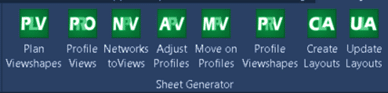
CIM Project Suite’s Sheet Generator workflow is a set of tools to speed up and increase the flexibility of the sheet creation process.
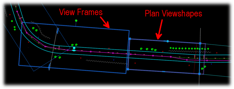
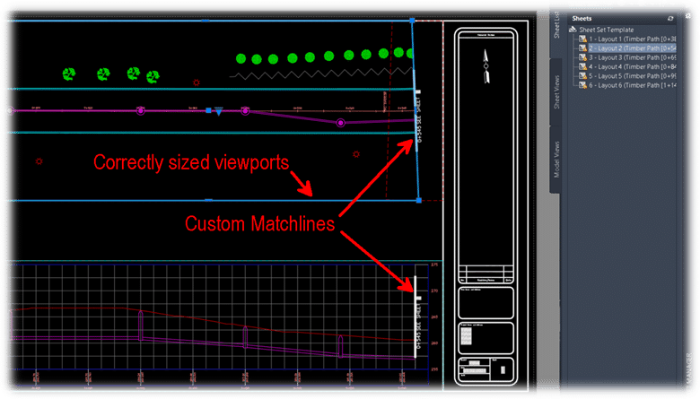
Native View Frames vs. CTC Software’s Plan Viewshapes
Plan Viewshapes consist of a block to represent the extent of your allowable viewport area in a sheet and a polygon to represent the actual shape and positioning of the viewport you would like to create. No more chopping View Frames at matchlines and hatching the rest of the rectangular area in your sheets.
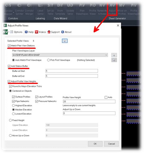
Creating profile views natively vs. with CTC’s CIM Project Suite.
This is a bit of a trick comparison because the Sheet Generator workflow takes advantage of the native tools for creating profile views. Although, Sheet Generator offers much more mass editing controls for profile view heights, stationing, and object projection. These tools give you the ability to have uniformity across any number of profile views, and have lots of flexible options for centering these profile views on key information.
The sheets that are created from CTC’s workflow will pull from company templates for sheet layout, and integrate into Sheet Sets seamlessly. The previously specified Plan Viewshapes and Profile Viewshapes create polygonal viewports with custom matchline blocks. The layout creation also adds north arrows, names layouts, and adds sheets to sheet sets automatically.
The most important part of this workflow is that if the linear design changes in any way, all the sheets can be updated. Not recreated but updated! This means that custom notes and legends, details and blowups will all stay in the layouts. Updates to viewports, north arrows, stationing, matchlines, layout names, and sheet set information all take place automatically when the layouts need to incorporate a design change. This iterative flexibility is a game changer for large projects, it eliminating human error, and executing massive changes to sheets with just a few clicks.
I hope the Sheet Generator workflow peaks your interest and helps you to find a new level of intuitive automation for your projects.
CTC also has great tutorials for all their tools on their Youtube Channel.
L’article de blog d’aujourd’hui présentera des outils spécialisés à l’arpentage, accélérant d’une part la production de vos plans dans Civil 3D et d’une autre part l’élaboration de vos gabarits. Nos objectifs :
Vous offrir une plus grande liberté dans la manipulation de vos levés terrains.
Transformer des heures en étiquetage de plans à quelques minutes par automatisation.
Créer et mettre à jour rapidement vos gabarits d’arpentage à l’aide d’éditeurs tabulaires.
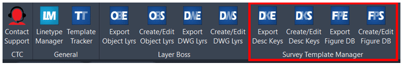
Côté outils de production, nous utiliserons Feature line to Alignment, Survey Sweeper, Point File Converter et Label Genie de la suite d’outils CIMProject développée par CTC Software.
Côté outils pour création et gestion de gabarit, nous utiliserons le panneau Survey Template Manager de la suite d’outils CIMManager développée par CTC Software.
Plus grande liberté à manipuler vos levés terrains
La suite CIMProject comprend quelques outils pour manipuler votre donnée du terrain, comblant quelques manques des outils par défaut de Civil 3D. Deux d’entre eux sont d’ailleurs gratuits (restent accessibles après la fin de la version d’essai), soit Feature line to Alignment et Survey Sweeper.
Feature line to Alignment est un outil simple qui permet de convertir une ligne caractéristique de terrain ou une figure topographique vers un Axe avec ligne de profil en long basé sur les élévations de la ligne. Cette option de conversion peut être très pratique pour produire des vues de profil d’un levé terrain sans passer par la création de surfaces 3D, ou de convertir rapidement un centre-ligne de route levé en alignement pour produire un nouveau design.
Survey Sweeper sert activement les utilisateurs des bases de données topographiques, en donnant une option pour supprimer simultanément des points et des figures topographiques dans un dessin et dans la base de données auxquelles ils sont liés. Les correctifs sur les points topographiques et figures dans un dessin créent des doublons dans la base de données, en gardant une copie de la donnée « erronée », et sont réinsérées dans le dessin si on réimporte les données. Il est donc très pratique de nettoyer tout d’un coup, en un seul bouton.
Point file converter permet de faire une conversion des levés terrains exportés en ASCII (ex.: en format TXT, ASC, CSV, etc.) pour passer ces points d’une liste de codes de points à une autre. À partir d’une table de transition, éditable par l’utilisateur, il est possible de convertir n’importe code ponctuel ou linéaire dans un autre système. En d’autres mots, cette fonction est un outil de « recherche et remplace » hyperefficace pour passer de vos standards de levés à celui d’un client.
L’étiquetage fait partie intégrante du processus de mise en plan.
En arpentage légal, on indique :
Les mesures de surfaces et périmètres d’un lot;
L’orientation et la longueur de segments limites de lots;
Des points cotés sur une surface;
Des cotes d’élévation sur des courbes de niveau.
En arpentage de construction, on souhaite identifier :
Des glissières;
Des murs de soutènements;
Des points de repères ainsi que leur position par rapport au chaînage d’un axe routier.
Peu importe votre branche de l’arpentage, l’étiquetage est un processus manuel lourd et répétitif, mais nécessaire pour produire un plan clair.
Label Genie permet d’écourter l’application manuelle d’étiquettes en automatisant leur processus de placement.
Par son « filtrage par calque », cette fonction peut appliquer « en masse » des étiquettes Civil 3D en utilisant les styles d’étiquettes de vos standards. Alternativement, des étiquettes personnalisées en MTEXTE d’AutoCAD pourront aussi être produits sur des objets normalement non-couverts par Civil 3D, comme les profils types et les polylignes. Toute étiquette produite par Label Genie est dynamique et annotative, comme toute étiquette de Civil 3D.
Label Genie peut placer des étiquettes sur le dessin courant et/ou tout autre dessin au choix, étiquetant en option les références externes associées. Dans le cas d’un étiquetage sur plusieurs dessins en simultané, Label Genie tient toujours en considération le dessin courant pour les options de styles de textes et d’étiquettes, et copiera les éléments nécessaires afin de les appliquer dans les autres dessins sélectionnés.
Sur le plan de l’application automatisée des étiquettes, l’utilisateur peut faire des combinaisons très variées d’objets « cibles » et de d’objets « sources ». Par exemple, il est possible de placer des étiquettes de surface, comme de points cotés ou de pente, à tous les vertex ou les centres de segments de toutes les polylignes sur un calque donné. Les possibilités de combinaisons sont innombrables.
De plus, si votre dessin évolue, on peut simplement « mettre à jour » les étiquettes spécifiées pour remplacer les étiquettes obsolètes avec de nouveaux emplacements ou un nouveau contenu, en évitant un nettoyage à grande échelle.
Créer et mettre à jour rapidement vos gabarits d’arpentage
Avec Survey Template Manager, vous pouvez gérer vos jeux d’identificateurs de description (liste liant vos codes de points à vos styles de points) et vos préfixes de figures (base de données liant vos codes de points à vos styles de lignes) dans une grille Excel.
Ces grilles Excel incluront des listes déroulantes avec toute information nécessaire à bâtir ou modifier ces listes (styles, calques, étiquettes, etc.), dans un environnement beaucoup plus pratique que celui proposé par Civil 3D, permettant de copier/coller, modifier ET supprimer en masse les lignes des grilles. Les grilles peuvent ainsi être modifiées dans Excel et réimporter via Survey Template Manager dans Civil 3D pour créer de nouvelles listes ou mettre à jour des listes existantes.
Les outils pour arpenteur des CIM Project et CIM Manager nous offrent une plus grande liberté dans la manipulation et l’étiquetage de nos levés terrains, et sauvent un temps considérable aux utilisateurs en réduisant les manipulations répétitives sur l’étiquetage et la gestion de leurs gabarits. Peu importe la taille, la complexité ou l’évolution dans le temps de vos plans de levés terrains, ces outils spécialisés vous permettront d’adapter très rapidement à l’évolution de vos projets. Vos dessinateurs et chargés de projet vous en remercieront!
Pour en savoir plus sur la suite d’outils CIMProject de CTC Software :


 Once the QTO is set up, we can also save the setup to a template to share among projects. This speeds up the QTO process even more for future projects.