• Tool Palette: Open File or Web Page

    Tool Palette: Open File or Web Page

    Do you have CAD standards document or web page you’d like to make easily accessible to your AutoCAD users?  Does it make sense to create a Tool Palette button for this?  If so, read on.

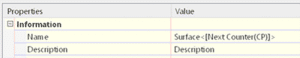
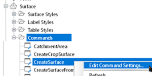
    Create a tool palette as usual or edit an existing palette.  Add a new tool to it, such as a line.  It will look like this initially.

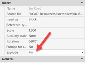
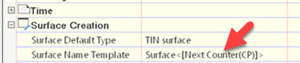
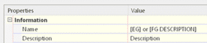
    Edit the properties of that tool and change three things. Reveal your inner artist when creating the icon image. Right-click to change that image.

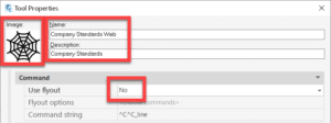
    Change the command string to do what you’d like the tool to do.  The syntax depends on whether you’d like to open a file or a web page.  The startapp function will use the appropriate Windows app for the selected file type.  In the example below, the PDF will open in Bluebeam Revu because that is my computer’s default PDF application.

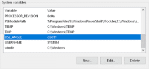
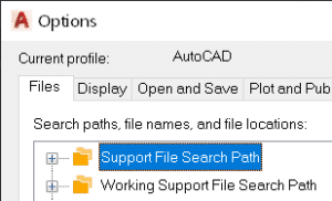
    You’ll notice I have no path defined for the PDF.  The findfile function looks for the file in the AutoCAD Support File Search Path (AutoCAD Options).  As long as you have the intended path defined here, the file will be found.  The path to the file can most certainly be hard-coded if you prefer.

    To open a file:

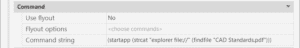
    (startapp (strcat “explorer file://” (findfile “The Actual File Name.pdf”)))  If the findfile option is appropriate)

    (startapp “explorer file://c:/temp/The Actual File Name.pdf”)  If the hard-coded path option is appropriate)

    To open a web page:

    ^C^CBROWSER;https://www.solidcad.ca/services/;

    My command string looks like this for the PDF option.

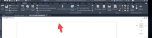
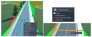
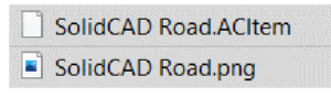
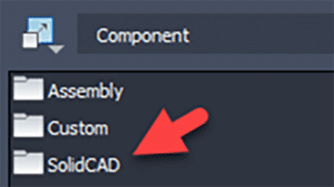
    Here are my two buttons.

    Enjoy!

    Civil 3D: New Geotechnical Modeler

    Civil 3D: New Geotechnical Modeler

    Autodesk has released a new extension for Civil 3D 2022 called the Geotechnical Modeler.  It replaces the former extension named the Geotechnical Module, which was developed by Keynetix and acquired by Bentley.  The last version of the former extension worked with Civil 3D 2021.

    Today, Autodesk delivered a webinar outlining the functionality of this new extension.  If you missed it, you can watch the recording here.  There is also a short video here on YouTube.

    Here is the online help document.


    Once installed, you’ll find sample data in this folder %PROGRAMDATA%\Autodesk\C3D-GeoTechModeler-2022\SampleData.


    Civil 3D: Edit a DREFd Object with No Source

    Civil 3D: Edit a DREFd Object with No Source

    You have a drawing containing an alignment that was data referenced. The source drawing cannot be found, and you need to edit that alignment. How to do this? Read on.
    Here you see the broken reference. The alignment can’t be edited or promoted.

    Follow these steps:

    1. Export the alignment to a LandXML file.
    2. Start a new drawing and import that LandXML file.
    3. Create a Data Shortcut to that alignment in the new drawing.
    4. Open the original file and replace the existing alignment with the new Data shortcut. There is no more broken reference; the alignment source is now the newly saved drawing.

    5. Open the new drawing and make your edits there as you normally would, remembering to synchronize the DREFs.

    Enjoy!


    Civil 3D: Sharing Assemblies

    Civil 3D: Sharing Assemblies

    So, you’re the technical team lead for your Civil Engineering firm, and you need to share amongst your team some Civil 3D Assemblies.
    You know how to create an AutoCAD tool palette, and you know that this is the best place to share assemblies – but you’ve tried, and it’s not working.

    If you’d like to learn how this is done read on.
    Palettes can be exported and then imported onto users’ machines, but when an assembly is edited, the creator must export again and then all the users must again import. This is not efficient.

    The Hard Way

    The method that Civil 3D uses to store assemblies on a palette works well, but to set it up is a bit of a bear.  Open this document to see the full details.  Here is a summary:

    • When an assembly is dragged to a tool palette a new DWG is created on your system. For my system this is:
      C:\ProgramData\Autodesk\C3D 2022\enu\Assemblies\Metric
    • You can create a tool palette with custom assemblies, sure, but you need to make these drawings available to your users. Usually, this means copying them to a network shared folder.
    • Even when you make them available, the DWG path must be defined in an ATC file that defines the palette, This is XML programming language and it can be difficult to find and disastrous if an error is made.

    The Easy Way

    I won’t say this is “The Best” method, but I believe it to be the easiest, quickest, and most foolproof method; and it’s the one I choose to use at this time.

    I won’t go into detail about how to perform each of these steps; it is assumed you know the technique. The short answer is that each assembly will reside in its own DWG file and that file will be stored in the shared network folder. That file will be a block in the tool palette.

    Open a drawing that conforms to your Civil 3D standards. Possibly one that already contains your desired assembly. 

    1. If the assembly has yet to be created, create it. 
    2. Ensure it is on the desired layer. Assign the desired code set style to it. Move it from its insertion point to 0,0. If this last step is skipped, the assembly will not be inserted properly later.


    3. Save the drawing to your shared network folder.


    4. WBLOCK and select the assembly and subassemblies together.  Ensure the insertion coordinates are 0,0,0 and provide the file name.  Click OK to create the drawing.


    5. Create a new tool palette or set current the destination palette for your new assemblies.  Drag the newly created drawing into the palette.

    6. To use the new assembly, drag it from the palette into a new drawing.  This will be a block, however.  It will need to be exploded once.

    7. You may suggest turning on the Explode option in the tool to avoid the explode step.  Indeed, I thought of that as well.  Problem is, this is what you get!


    That’s it.  Once the assemblies have been created, it takes about 45 seconds per assembly to add to the palette.  If edits are required, simply open the appropriate DWG, make the edits, and save.


    Civil 3D Styles: Object Naming Defaults

    Civil 3D Styles: Object Naming Defaults

    So, you’re in charge of your company’s Civil 3D standards and drawing template and you’re annoyed when users don’t use the documented naming convention.  Read on to find out more.

    Users will typically do what’s easiest, especially when the heat is on from an impending deadline.  They don’t always take the time to find the standards manual and read the proper section when they’re not sure if they’re doing the right thing.

    When Civil 3D objects are created, they all need names.  We’ve all seen Alignment(12) and Surface(235).  These are terrible names!  Road A and Existing Ground would be better, respectively.  While it’s great to have a documented standard, why not have something in the users’ faces, Just-In-Time, when they are creating the objects?

    Here is the out of the box naming scheme for surfaces.  Surface<[Next Counter(CP)]>, where Next Counter would be 1, 2, 3, etc.

    The default for this can be changed in the Settings tab.


    Why not set up the default with a hint to the desired name(s)?  in this case, the user would use one of two conventions.

    • EG
    • FG Road A Corridor

    This same technique can be used for every Civil 3D object as they all have settings for default names.  I’ll let you decide on what a good default would be, but it will help your users more easily conform to your standard.  Just sayin’.

    As a bonus tip, consider creating these objects in your template with their names already defined.  When a user starts a new file using that template, the objects will already be there available to be edited and already named with pertinent descriptions.  This technique may not work for everything, but it certainly works for quite a few.


    Civil 3D: Grading Optimization Problem

    Civil 3D: Grading Optimization Problem

    Do you have an issue displaying the Grading Optimization (GO) window with Civil 3D 2022.1 and GO 2022.2?  If so, read on.

    I have been working with GO since it arrived, but when I installed the Civil 3D 2022.1 and GO 2022.2 updates, GO failed to display once I click “Optimize”.  The windows actually appear, but only the shadow edge.


    Autodesk is working on a public fix, but they asked me to try this, and it worked.  Create a new Windows Environment variable with this name and value.

    Variable:              USE_ANGLE

    Value:                  d3d11

    Infraworks: Custom Assemblies

    It’s relatively easy to create a custom component road assembly within an Infraworks model.  But how does one save that custom assembly for use later?  Read on to find out!

    The answer depends on how you’d like it to be shared:

    • Export for use in other existing models.
    • Save for use when new models are created.


    Saving the Assembly

    First, to save a custom assembly, simply right click the component road and choose Add to Library.  Choose a station to copy and give the new assembly a name.  The new assembly will appear in the style palette.

    Choose a station to copy and give the new assembly a name.  The new assembly will appear in the style palette.

    Export for Existing Models

    The individual assembly cannot be exported, but the catalog can.  Select the catalog, in this case, Custom, and click to export to a JSON file.

    The JSON file can then be imported into a different existing model using the import button.  The assembly will be available in the styles palette.

    Save for Future Models

    There is no “tool” for this, but if one copies the appropriate files from and to the correct locations, then it works just fine.  The custom assembly files can be found in the model’s folder path.

    …model.files\unver\Content\Styles\Component\  .  Possibly in a Custom sub-folder.

    There will be 2 files for each assembly.  A PNG image and a ACItem file.

    Copy these two files to the Infraworks standard folder.  Feel free to create a sub-folder here to place your custom assemblies.  This folder will appear within Infraworks.

    C:\ProgramData\Autodesk\InfraWorks\Resources\LocalLibrary\Styles\Component\

    The JSON file can then be imported into a different existing model using the import button.  The assembly will be available in the styles palette.


    Create Easy Surface Statistics Labels with Dynamo

    In this blog, our Civil/Infrastructure Technical Product Specialist, Jae Kwon, will cover how a Civil 3D user can use an automatic way to create surface statistics labels with Dynamo.

    Instead of Civil 3D users manually labelling surface statistics for his surfaces with a manual process, they can explore an automatic way using Dynamo. Let’s take it further below by comparing the existing manual method versus the Dynamo Solution.


    Existing Manual Method

    The existing method by the user was the following:

    1. Open the surface properties, navigate to the statistics tab, right click and “copy to clip” the contents

    2. Paste the info into notepad and rearrange the text to get the desired format

    3. Copy-paste the info into an Mleader pointing to the surface.

    This method works, but there is a lot of manual formatting involved every time, and this has to be repeated every time there is a surface update.

    Also, we cannot create a surface label style for this kind of label since there are no statistics properties we can pull from the surface labels (spot elevation, contour and slope).

    Now, let us look an automatic solution to this via Dynamo.


    Dynamo Solution

    First, we get the user to select the surface they want to label with a simple drop-down list. This may be done through either the Surfaces node from the Civil 3D Toolkit (shown below) or a UI package like Data Shapes.

    Next, we extract the statistics with the Surface TerrainStatistics node.

    The statistics can then be formatted with various text manipulation nodes. But where can we inject this text where one of the surface labels can access it? The answer is surface description! For most of us, the surface object’s description field goes largely unused, and it serves as the perfect place to store the statistics data.

    When a spot elevation label that shows the surface name and description is used, it looks something like this:

    Just a general note: The surface statistics can also be stored on the surface as a property set.

    If the surface undergoes any changes, we can update the statistics data stored in the descriptions (and the property set) by simply rerunning the same Dynamo script with a click of a button.


    Conclusion

    Dynamo has become the primary tool for many power users to automate various tasks in Civil 3D because it is so easy to put together.

    We saw how surface statistic labelling may be done with Dynamo including:

    • Extracting and formatting surface statistics 
    • Storing the formatted data in the description and/or property set
    • Accessing this data with any one of the available surface label styles 
    • Easily updating the data by simply rerunning the Dynamo script

    If you need a solution to any Civil 3D project, we would be glad to help and find a specific Dynamo solution for you. Reach out to us at info@solidcad.ca

    Autodesk Desktop Connector Update – June 2021

    June 1, 2021 (v. 14.10.0.1456)

    Do you use BIM 360 and AutoCAD products?  Do you have the Autodesk Desktop Connector installed?  If so, there is a new update.  This may not be news to you as there are frequent updates, but this one is somewhat unique.  Please read on.

    Please review this article regarding some changes that may affect your IT services. Also, see the official release notes.

    New Feature:

    The new Reference Explorer provides the ability to visualize all files in a dataset as well as the relationships between the files before or after uploading to the cloud.


    Resolved Issues:

    • DST files will not open, and content is incomplete after the DST file is saved to the workspace, or when synced from the cloud.
    • Increased the number of concurrent files in download workflows to increase performance.

    Civil 3D 2020.6 Update

    Fixes, and of course new features are included with this update.  Here are the release notes.  Read on to discover what’s new.


    Fixes

    There have been many defect fixes and you can read about them here.  The one notable item I’ll describe here is about feature lines.  Some users have experiences them magically disappearing from some drawings.  Here is an excerpt form the documentation:

    “Errors that will lead to missing feature line issue are automatically detected and fixed when opening a drawing. This operation will only run when Civil 3D detects a potential error in the drawing.”


    New Features

    Read about the new features here.

    Feature Lines:

    • Use the Insert Points at Crossing Locations command to insert PIs or elevation points on crossing feature lines in the same site.
    • Use the Set Grade/Slope Across Feature Lines command to edit the grade or slope between vertices on two or more intersecting feature lines.
    • Use the Set Corridor Baseline Elevation by Reference command to set the elevation of a point on a feature-line-based corridor at a given grade or slope from a specified location. This command adjusts the elevation of the corresponding PI on the corridor baseline accordingly.


    Autodesk Collaboration (BIM 360):

    • Support has been added for reference templates and sheet set data files.


    ArcGIS:

    • Refresh an ArcGIS dataset in your drawing so that it matches the ArcGIS dataset online and add new Civil 3D objects to ArcGIS.

    Pipe Networks:

    • Gravity network analysis has 2 new settings:
      • Pipe Length Type which you can use to specify the pipe length type to use for the analysis calculations.
      • Conservative Travel Time that you can use to specify whether the minimum velocity or the calculated design velocity will be used to calculate the pipe section time if the design velocity is smaller than the minimum velocity.