• Environmental Acoustics Inc.

    Success Stories

    Environmental Acoustics Inc.

    Located in Mississauga, Ontario, Environmental Acoustics Inc is an exclusive distributor of the LogiSon® Acoustic Network. This networked sound masking, paging, and music system is recognized as an industry leader that’s installed in hundreds of millions of square feet worldwide and earned numerous awards for innovation, performance, and ease of use.  Environmental Acoustics Inc. prides themselves in designing and installing “sound masking” systems that provide acoustic comfort and higher levels of speech privacy within the office, medical, and hotel environments.

    Automating AutoCAD’s design process with SolidCAD’s built-in plugin

    The Challenge

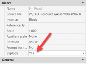
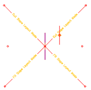
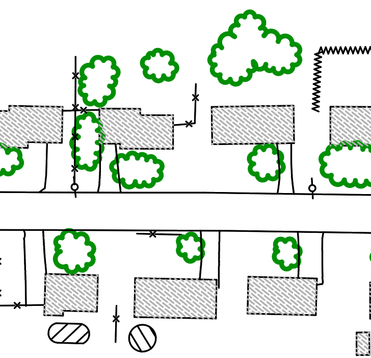
    Whenever Environmental Acoustics (EA) begins a new installation, they start their project by studying the building layout drawn as an AutoCAD file. Their experts identify required components (e.g., speakers, power supplies, etc.) and insert them as AutoCAD blocks. The EA experts use AutoCAD’s lines and arcs to model wires and connect them to the component blocks. However, because AutoCAD has no relation between components and wires, EA faced many challenges in having a clear and standard way to properly mark their AutoCAD files.

    Often, many of their experts worked on different installations at once, and each drawing would contain incorrect components or redundant wires that were once attached to a component that was either moved or deleted. This often resulted in a final AutoCAD drawing that contained various design errors.

    With a growing increase of errors, this also complicated the company from creating Bill of Materials (BOMs) since there was no standard way to quantify the wires used in any of their projects.

    The Solution

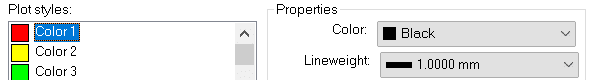
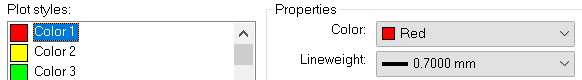
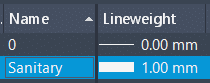
    After identifying the issue, EA turned to SolidCAD in need of a solution that would streamline their process and limit the number of errors and rework their design files. SolidCAD’s programming team developed an AutoCAD plugin that can be added to any AutoCAD version between 2018-2022. The plugin was built to show a list of available components which can be dragged and dropped into the AutoCAD file. The plugin also added a new command which allows users to select two components to wire them. Behind the scenes, the plugin uses the standard AutoCAD entities such as blocks, lines, and arcs which flatten the learning curve. This allowed users to only select from standard design options when adding components onto a drawing, which always ensured that every user followed the same design expectations for all their projects. In addition, the plugin was also designed intuitively that whenever a component was removed, it would automatically delete any incoming and outgoing wires attached.

    To help solve the issues of generating BOMs, SolidCAD ensured that the plugin automatically generated BOMs for components and wires that could easily be exported into Excel which would automatically contain any cost information related to the materials used in the installation.

    The Results

    After undergoing the process of assessing current procedures performed by EA, SolidCAD was able to help EA to:

      • Generating BOMs from 30 minutes into milliseconds
      • Standardized design files with the built-in component blocks while still allowing admin to add/edit/delete components as necessary.

    Testimonial

    SolidCAD’s development team delivered an AutoCAD plugin that not only improves our design process and eliminates errors, but also showed their commitment to delivering high-quality automation services.

    - Stan Klas,
    President at Environmental Acoustics Inc.

    Products & Services Used

    • Programming
      • AutoCAD
      • .NET framework to create AutoCAD plugin
      • C# to write the plugin
      • XAML to create UI

    Similar Projects

    Procepack

    PROCEPACK is a firm specializing in the purchase and sale of packaging and process equipment. They serve customers from a wide range of industries from food and cosmetics to pharmaceuticals. They leverage their vast and…
    Manufacture Scorpion Success Story

    Manufacture Scorpion

    Manufacture Scorpion is a manufacturer/distributor whose mission is to make the world’s best pneumatics and vacuum technologies available quickly and easily to North American companies. As the largest Pneumax partner, they have exclusive agreements with…

    RGTECH

    RGTECH is a specialty precision machining company. Founded in Lévis, QC by experienced industry professional, Rémy Gagnon, RGTECH works closely with several industries including the medical, optic/photonic and electronic industries to provide high quality parts…

    Civil 3D: Sharing Assemblies

    Civil 3D: Sharing Assemblies

    So, you’re the technical team lead for your Civil Engineering firm, and you need to share amongst your team some Civil 3D Assemblies.
    You know how to create an AutoCAD tool palette, and you know that this is the best place to share assemblies – but you’ve tried, and it’s not working.

    If you’d like to learn how this is done read on.
    Palettes can be exported and then imported onto users’ machines, but when an assembly is edited, the creator must export again and then all the users must again import. This is not efficient.

    The Hard Way

    The method that Civil 3D uses to store assemblies on a palette works well, but to set it up is a bit of a bear.  Open this document to see the full details.  Here is a summary:

    • When an assembly is dragged to a tool palette a new DWG is created on your system. For my system this is:
      C:\ProgramData\Autodesk\C3D 2022\enu\Assemblies\Metric
    • You can create a tool palette with custom assemblies, sure, but you need to make these drawings available to your users. Usually, this means copying them to a network shared folder.
    • Even when you make them available, the DWG path must be defined in an ATC file that defines the palette, This is XML programming language and it can be difficult to find and disastrous if an error is made.

    The Easy Way

    I won’t say this is “The Best” method, but I believe it to be the easiest, quickest, and most foolproof method; and it’s the one I choose to use at this time.

    I won’t go into detail about how to perform each of these steps; it is assumed you know the technique. The short answer is that each assembly will reside in its own DWG file and that file will be stored in the shared network folder. That file will be a block in the tool palette.

    Open a drawing that conforms to your Civil 3D standards. Possibly one that already contains your desired assembly. 

    1. If the assembly has yet to be created, create it. 
    2. Ensure it is on the desired layer. Assign the desired code set style to it. Move it from its insertion point to 0,0. If this last step is skipped, the assembly will not be inserted properly later.


    3. Save the drawing to your shared network folder.


    4. WBLOCK and select the assembly and subassemblies together.  Ensure the insertion coordinates are 0,0,0 and provide the file name.  Click OK to create the drawing.


    5. Create a new tool palette or set current the destination palette for your new assemblies.  Drag the newly created drawing into the palette.

    6. To use the new assembly, drag it from the palette into a new drawing.  This will be a block, however.  It will need to be exploded once.

    7. You may suggest turning on the Explode option in the tool to avoid the explode step.  Indeed, I thought of that as well.  Problem is, this is what you get!


    That’s it.  Once the assemblies have been created, it takes about 45 seconds per assembly to add to the palette.  If edits are required, simply open the appropriate DWG, make the edits, and save.


    Importing wire types in AutoCAD Electrical

    Figure 1

    Whenever we are working with AutoCAD Electrical, one of the key features that we have when we are creating our drawings, is the ability to

    create and assign the custom wire types that we will use throughout our schematic designs. Every time that we create a new drawing, by default the only wire that is going to be available is the WIRES layer which is the generic wire type that the software uses when we first create any type of wire as displayed on Figure.1 in the Create/Edit Wire Type editing window.

    Having to manually enter the types of wires that we are going to use is a task that cannot be avoided the very 1st time that we create a drawing, but once we having created the list of wires that we need to use in one drawing, we can reuse them over and over again.

    To achieve this we need to do the following:

    • Open the Create/Edit Wire Type editing window and click on the icon that says “Import” as seen on Step 1 on Figure 2.
    • A window will pop-up asking you to browse to the drawing that contains all the wires information, browse to the desired drawing.
    • Once we have selected the DWG another window will pop-up displaying all the wires from that drawing.
    • By default all the wires from that drawing are selected and highlighted in black as seen on Step 2 on Figure 2.
    • We can pick and choose the wires that we want to import and the click OK to complete the process.

    Figure 2To take this one step further, we can standardize the wires that we use with your CAD Manager so we can import that list of wires directly into your templates. To achieve this we need to open the current template as a DWT file, then repeat the exact same process that was described earlier.

    Once we have completed importing all the wires we need to re-save the template as a DWT one more time to make sure it will be usable as a template in the future.

    This will further standardize the wires that the designers are required to use and remove the guess work by setting the wires at a template level.


    Enabling The Navisworks Plug-In in Plant 3D

    In my previous blog, I explained how Navisworks can complement Plant 3D.

    Now I will show you how to enable some Navisworks features directly within Plant 3D, or any AutoCAD based products. With this feature enabled the user can export a Navisworks (NWC) file directly from within AutoCAD. They will also have the option to manage the Navisworks export settings.

    For this example, I will be using AutoCAD Plant 3D 2021 and Navisworks Manage 2021. If you do not have access to Navisworks you can download the Navisworks exporters from Autodesk directly.

    Here is the link: Navisworks 3D Viewer Free Download | Navisworks Freedom (autodesk.com)

    Loading the Plug-in in AutoCAD

    1) Open or create a new DWG in AutoCAD.

    2) In the Command line, type APPLOAD

    3) Navigate to: C:\ProgramData\Autodesk\ApplicationPlugins\autocad_exporter2021_x64.Addin.bundle\nwexport2021

    4) Select crx

    5) Click on Load

    6) It will inform you if the Plug-In was successfully loaded.

    7) To test it, start typing NW in the command line. A new set of Navisworks commands should be available.

    8) To export DWG contents, simply type NWCOUT and save the file.


    Adding the Navisworks Menu in AutoCAD

    With AutoCAD or a DWG open, type CUILOAD in the command line:

    1) Click on Browse

    2) Navigate to: C:\ProgramData\Autodesk\ApplicationPlugins\autocad_exporter2021_x64.Addin.bundle\nwexport2021\nwcreate_data18

    3) Change the File type to “Legacy Menu Files”

    4) Select mnu and click open.

    5) Click on Load

    6) Close the CUI dialog box. If you get a warning message, it is ok to proceed.


    If you would like to learn more, Navisworks training is available as a supplementary course to SolidCAD’s Plant 3D course curriculum. Please contact training@solidcad.ca

    Dynamic Duo – AutoCAD Plant 3D and Navisworks: How to view Plant 3D data in Navisworks

    In a data driven world, information can be the currency that can make or break your project. Misinformation, or the lack of, can cause delays and costly errors in a project’s life cycle.

    AutoCAD Plant 3D is a powerful process-piping design tool. Each piping component placed in Plant 3D has useful data embedded in it. This data is crucial for the plant’s overall design. However, this data can only be viewed within the Plant 3D application.

    In plant design, data will pass through many hands and in various stages of the project. How do we then share this information to external parties like clients, fabricators or constructors who don’t have the Plant 3D application?

    This is where the dependable sidekick comes to the rescue. Navisworks!

    Navisworks has the ability to open various file types. It can also read embedded data if the proper object enabler is installed. Fortunately, Autodesk has one specifically for Plant 3D. You can download the 2021 version here.

    Here’s an example of a Plant 3D model in Navisworks without an object enabler. You can see that some shapes aren’t displayed properly, and it is not reading the embedded data.

    Here is the same Plant 3D model with the object enabler installed. All the components are displayed correctly, and the embedded data is being displayed in the properties section.


    With the Plant 3D model in Navisworks, the file can now be saved as an NWD file and delivered to external parties. All they need is Navisworks Freedom to view the file, which can be downloaded for free from Autodesk.

    This is one of many features available in Navisworks. Apart from a robust 3D viewer it can perform tasks such as clash detection and animation.

    If you would like to learn more, Navisworks training is available as a supplementary course to SolidCAD’s Plant 3D course curriculum. Please contact training@solidcad.ca

    In the next blog, we will look at how to utilize the Navisworks plug in within Plant 3D. Stay tuned!

    Migrating Versions in AutoCAD Electrical

    Every year Autodesk releases a new version of the software which often contains new features, bug fixes and overall improved stability, so a common question that we get from our customer is: how do I move all my custom settings, symbols, databases, etc. to the new version of AutoCAD Electrical. Included with AutoCAD Electrical is the “Migration Utility” which allows the user to move all your customized settings, custom libraries (symbols + icon menus), databases, etc. This utility can be found inside the “Project” tab as displayed on Figure 1.

    Figure 1

    In this blog article we will cover the steps requires for us to upgrade and migrate from one version to another. Once we have downloaded and installed the new version of AutoCAD Electrical, we close all other Autodesk software that so we can start the “Migration Utility”.

    Figure 2

    In this configuration window we are required to select the previous version that we want to migrate from. Clicking on the dropdown arrow will display all the previous versions installed on the local machine. If you have more than one version installed, you need to select the software version that has all the latest customization/libraries of the software as seen on Figure 2.

    After we select the version that we want to migrate from, the next step is to select the items we want to migrate. Those items can be found under “Migration items” and, by default, all of them are going to be selected as seen on Figure 3. If we click on any of the individual items, we will find the option to copy or merge the pre-existing information. Keep in mind that each migration item might have a different preset value here so make sure you review all the items that need to be migrated.

    Figure 3

    Once we have reviewed all the migration items we need to click “OK” so the migration process can start.

    Figure 4

    Before the migration gets started, a “Migration Review” window is going to popup with a summary of all the files that are about to be migrated as seen on Figure 4.

    After a final review we are ready to click “OK” so the migration process can start.

    While the migration is in progress, a window is going to popup showing the file currently being migrated and the current progress status as seen on Figure 5. Keep in mind that depending on the size of your customized files (databases, etc.), this process could take from minutes to several hours.

    Figure 5

    When the Migration is complete a summary window similar to the migration review will popup specifying, once again, all the files that were migrated.

    The last step is to restart the software so you will be ready to use your new version of AutoCAD Electrical without losing any preexisting customized files/settings.

    Autodesk Desktop Connector Update – June 2021

    June 1, 2021 (v. 14.10.0.1456)

    Do you use BIM 360 and AutoCAD products?  Do you have the Autodesk Desktop Connector installed?  If so, there is a new update.  This may not be news to you as there are frequent updates, but this one is somewhat unique.  Please read on.

    Please review this article regarding some changes that may affect your IT services. Also, see the official release notes.

    New Feature:

    The new Reference Explorer provides the ability to visualize all files in a dataset as well as the relationships between the files before or after uploading to the cloud.


    Resolved Issues:

    • DST files will not open, and content is incomplete after the DST file is saved to the workspace, or when synced from the cloud.
    • Increased the number of concurrent files in download workflows to increase performance.

    AutoCAD Printing and CTB

    Do you use more than one CTB file when printing in AutoCAD?  More than 10?  40?  What if I said you really only need 1, the Monchrome.ctb file?  Read on to find out how…

    If you already understand CTB files, feel free to scroll down to the heading “Do This Instead”.

    Let’s look at what we have to work with:

    1.AutoCAD users use various colours.

    2.Typically, the colours used are chosen from this 256-colour “Index” palette.

    3.Those colours on the screen don’t always print that colour.

    4.Linework need to print to varying widths.

    On-Screen:

    Printed:

    CTB files are the intermediary between the drawing on screen and the final printed product.  If one is not used, what you see on screen is what is in the print.  They are used to transform what is seen on screen to what is displayed in the print.


    Many AutoCAD users rely on several CTB files to print documents to various regulatory standards.  Here is why…

    • The City of SolidCAD requires a sanitary sewer layer to be red on screen but print black and thick (1mm).
    • The District of Cansel requires that same sanitary layer to be red on screen but print red and not so thick (0.7mm).
    • 42 other standards exist and a unique CTB file is required for each of them.

    Here is the SolidCAD CTB file:

    Here is the Cansel CTB file:

    THESE ARE NOT REQUIRED!


    Yes, that was a little tongue-in-cheek.  Sometimes you’re sent a file and you just need to print and use the available CTB.  But if you have the time, inclination, and desire to make things a little easier on yourself, understand it’s possible.


    Do This Instead

    The solution here is actually very simple.  Follow these steps.

    1.Set the line weight properly for the layer based on the regulatory body standard.

    2.Use the out of the box monochrome.ctb file.  This file prints all 256 Index colours in black.

    How to print hat sanitary layer in red when the CTB file prints all colours black, you ask?  Well, I didn’t say the CTB prints all colours black, just the 256 Index colours.

    3.When colour is required set the layer colour, not to one of the 256 Index colours, but to one of the 16.7 million True Colours.

    4.You need to print a grey shade?  Again, choose a True Colour; just choose a colour at the very bottom.  Use the slider on the right to control the shade.

    You see, the CTB file does not control the output of True Colours, only the 256 Index colours.

    Enjoy!

    Create Your Own AutoCAD Tutorial Library

    Are you or do you have a staff member in your office who likes to create tutorial content?  Or maybe you simply have some web links to which you’d like to regularly refer.  Maybe you’d like to share these tutorials with the rest of your AutoCAD team.  Sure you can tell them where the videos, documents, or web links are, but the users must open them outside of the AutoCAD environment.

    What if the users could access this content right within AutoCAD?  The closer the help is to the user, the better, I always say.  Consider creating a custom tool palette containing buttons to open these tutorials, and sharing it with the users.

    I’ll go on the assumption you already know how to create and share a tool palette.  I’ll show you how to create tools that link to files or web links.

    Create the Tool

    Drag a line or a text object to your new tool palette then edit its properties.

    Web Link

    Edit 5 properties:

    • Name.
    • Description.
    • Specify Image.
    • Turn off the flyout option
    • Edit the Command String.  Enter this information ^C^C_browser https://WebLink  Paste the link after browser.

    File

    The only difference between this tool and the web link is the Command string which uses a little LISP code.  Enter the path to your file after findfile, within the quotes.  DO NOT use back slashes, only forward slashes.

    • ^C^C (startapp “explorer.exe” (findfile “C:/temp/1.docx”))

    That’s it.  Make it easy for your users to get the help they need!


    Infraworks 2021.2 Update

    Autodesk has released the next update for Civil 3D 2021.  Find the release notes here.  Here are some highlights:

    • Add decorations to component roads imported from Civil 3D.
    • Modify lane markings for component roads.  No lane marking shadow issues.
    • Various improvements to Civil Structures.
    • A new Home screen including Recent and BIM 360 tabs.
    • Select a coordinate system during model creation using the Model Builder.
    • Add a point cloud in LAS or LAZ format without first saving an RCP file.