• Civil 3D: Model Existing Underground Utilities Efficiently

    Civil 3D: Model Existing Underground Utilities Efficiently

    Must you draw existing gas, tel, and other similar underground utilities for your projects?  If you’re not using the technique described below, you’re using too much time!  Read on to find out more.

    Join us at Infrastructure University, session 3, on October 20th for more information about this technique. For now:

    Facts:

    1. For nearly every civil engineering project, we must identify existing features on our construction drawings so they may not be disturbed during construction and so we may design proposed works without conflicting with these existing features. They must appear in both plan and profile.
    2. It can take considerable time to draw and label them in the plan, and even more project them into profile.
    3. When there is an edit to the alignment, the profile locations must be recalculated, taking more time.
    4. Experiments have shown that it can take 84 seconds to draw each utility. Then 26 more seconds each when the alignment is edited.
    5. Using the technique described below, the time is reduced from 84 seconds to 20 seconds. But 0 seconds when the alignment is edited.
    6. For 160 utilities:
      1. 3.7 hours using the manual technique.                   69 minutes each time the alignment is edited.
      2. 53 minutes using the automated technique.         No extra time when the alignment is edited.

    Method

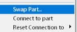
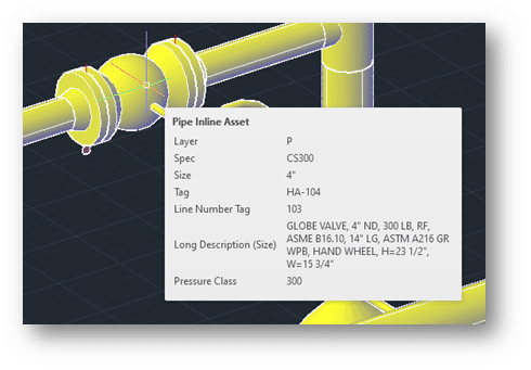
    1. Create pressure network parts lists, one for each utility. Assign styles accordingly.
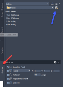
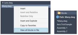
    2. Create pressure networks, one for each utility. Assign the parts list and label styles accordingly.
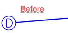
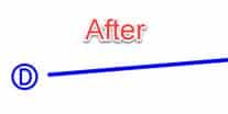
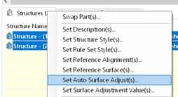
    3. Model the existing utilities as pressure networks and project them into profile. The depth below ground can be automated.

    Civil 3D: Pipes not Extending to Structures

    Have you seen this before?  This is how Civil 3D’s pipes sometimes appear before and after the current annotation scale has been changed.  Not good.

    Read on to learn more…

    What is the cause?  This setting in the structure style.  You will find it in the Plan tab in the style editor.

    How to fix this?  There are several methods.

    • Never change the scale!  Easy to say, not so easy to implement.
    • Turn off that setting.  Problem is, you get this.

    • Swap each structure.  Choose the same structure.  What if there are 200 of them?  Too much time.

    • Grip-edit each structure and move them back onto their original positions.  Same problem as previous, too much time.
    • Add a wipeout to the block being used AND turn off that setting.  Our first real potential solution.  Some users report black blobs when printing to PDF when using wipeouts, however.
    • Use Project Explorer.  Select all the structures, right click, and choose the following option.  Then just click OK.  This kicks the structures in the butt and the pipes extend themselves properly.  Of course, next time the scale is changed, this must be redone but this only takes about 5 seconds.

    I prefer the wipeout option because it is permanent.  No other workarounds necessary.  If this is not an option for you, then the Project Explorer trick is likely the best option.

    Civil 3D: Alignment Creation – Free Entities

    Alignments are created in Civil 3D by selecting AutoCAD objects or by using specialized tools.  Sometimes selecting objects is appropriate, but when the alignment is required to be very flexible in terms of editability, utilizing those specialized tools can be critical.


    There are three types of Alignment segments present within those specialized tools: Fixed, Floating, and Free.  The use of these tools is not always obvious, so we have created 3 video which explains the use of them.


    The last of the three videos, Free Entities, can be viewed at this link or below.

    Civil 3D: Alignment Creation – Floating Entities

    Alignments are created in Civil 3D by selecting AutoCAD objects or by using specialized tools.  Sometimes selecting objects is appropriate, but when the alignment is required to be very flexible in terms of editability, utilizing those specialized tools can be critical.


    There are three types of Alignment segments present within those specialized tools: Fixed, Floating, and Free.  The use of these tools is not always obvious, so we have created 3 video which explains the use of them.


    The second of the three videos, Floating Entities, can be viewed at this link or below. Come back in a week or two for the next video.


    Civil 3D: Alignment Creation – Fixed Entities

    Alignments are created in Civil 3D by selecting AutoCAD objects or by using specialized tools.  Sometimes selecting objects is appropriate, but when the alignment is required to be very flexible in terms of editability, utilizing those specialized tools can be critical.


    There are three types of Alignment segments present within those specialized tools: Fixed, Floating, and Free.  The use of these tools is not always obvious, so we have created 3 video which explains the use of them.


    The first of the three videos, Fixed Entities, can be viewed at this link or below. Come back in a week or two for the next video.


    HOW OUR AEC E-LEARNING SOLUTION IMPROVES EMPLOYEE RETENTION

    This story was originally published by 

    AN AEC E-LEARNING SOLUTION CAN MAKE ALL THE DIFFERENCE FOR YOUR EMPLOYEES.

    Employee retention is one of the biggest ongoing goals for successful companies. Improving retention allows you to keep your top performers, promote from within, and avoid the time and cost of replacing staff.

    recent survey from The Harris Poll found that 70% of employees would likely leave their current organization if its training and development offerings weren’t up to par.

    Let’s explore how our AEC e-learning solution, Pinnacle Series, can help deliver the development employees are looking for and improve retention at your architecture, engineering, construction, or manufacturing organization.

    1. Promotes lifelong learning
    2. Makes workflows more efficient
    3. Personalizes training
    4. Empowers their career goals

    PROMOTES LIFELONG LEARNING

    Learning helps us grow and achieve goals throughout our lives and careers. But often, employees feel like they’re growing stagnant. If you provide the opportunity for them to learn new skills on their own terms, you’ll build the kind of culture that encourages growth.

    MAKES WORKFLOWS MORE EFFICIENT

    Pinnacle Series is full of training videos, documents, and other resources employees can use to improve their skills at dozens of important AEC programs e.g., software skills, company guidelines, health and safety knowledge, and more. And they can do it the minute they need answers, for instance, in the middle of a project. Instead of interrupting a co-worker, they can hop onto Pinnacle Series, watch a quick how-to video, and get back to work with confidence.

    PERSONALIZES TRAINING

    Employees often don’t benefit from a one-size-fits-all course enrollment or seminar that doesn’t fit their individual needs. They feel it’s a waste of their time. In addition, it can be labor-intensive for managers to figure out the required training needs for every employee, especially within larger organizations. With Pinnacle Series, the concept of personalized learning is built in. Users can take KnowledgeSmart assessments to generate a custom learning plan that fills their skills gaps without repeating information they already know.

    EMPOWERS THEIR CAREER GOALS

    By equipping your employees with new skills to move forward in their careers, you’re helping them and your organization. You can invest in and promote from within.

    Want to see for yourself how our AEC e-learning solution can help your organization? Schedule a demo or free trial of Pinnacle Series today!

    Are you a current Pinnacle Series customer? Log in now or connect with your Customer Success Manager to see how you can leverage our platform in your employee retention efforts.

    Civil 3D Assemblies: Tool Palette or Block Library?

    Civil 3D Assemblies: Tool Palette or Block Library?

    Civil 3D comes shipped with pre-configured assemblies that may or nay not fit your needs.  We created another BLOG post here to show how to create your own and share them with others in your team.  There is another way…read on.

    The Cole’s notes are:

    • Make a new drawing.
    • Create your assembly in this new drawing placed at 0,0.
    • Insert that drawing into your design and explode the resulting block.

    In the linked article above, we suggested creating a tool palette.  This works well for blocks so they may be placed on the correct layers.  For assemblies, since this block will be exploded, this is not a requirement.  Might there be an easier way?  There is.  You see, tool palettes require a little maintenance.  The trick below does not.

    AutoCAD’s Block Library

    In Civil 3D 2022 or later, open the new block palette introduced in version 2020.  The option I’m about to illustrate is not available with 2020 or 2021.  You will see two things: a Library tab (red) and a button to select a folder (blue).  Clicking the folder button will prompt you to select a folder containing drawings.  If each of those drawings is an individual assembly, your job is done.  Drag and drop one of those into your drawing and ensure it is exploded.  You’ve just inserted an assembly.

    No maintenance is required.  Just save a new drawing with a new assembly into that folder and the next time AutoCAD is started, you’ll see the new content.  If you prefer to have all assembly blocks defined in a single drawing, that’s fine too, simply right click the drawing and choose…

    Enjoy!

    AutoCAD 2023: New Release

    AutoCAD 2023: New Release

    It’s that time of year; Autodesk has just released the 2023 version of their flagship drafting application, AutoCAD.  Read on to discover some of the new features.

    Click to peruse Autodesk documentation.

    Compatibility

    Likely one of the most common questions is about compatibility.  AutoCAD 2023 remains in the 2018 format.  There is no need to save files to previous versions unless your recipient is using 2017 or earlier.

    Markups

    I’m intrigued by this feature more than any other this year. PDF markups are ubiquitous in our industry, but there were few tools to help manage them.

    In AutoCAD 2023, PDF markups can be overlaid and displayed more easily, and they can then be imported as a trace layer and converted to AutoCAD objects. Markup assist will use text recognition to add AutoCAD text, multileaders, and revision clouds from the PDF markup. Image file formats are also supported if the PDF is scanned and marked with coloured pens.

    Insights

    Machine learning provides tips and tricks when and where you need them.  AutoCAD generates macro insights based on your unique command usage.

    LISP

    LISP apps can be loaded and run within the AutoCAD web app.

    General

    The command line is visible within each active floating window.

    Count has been updated to enable easier navigation and selection.

    The Sheet Set Manager has been given a performance boost and has a new interface in Autodesk Docs.

    ANNOSCALEZOOM controls mouse zooming in paper space.

    MTEXT objects can be converted to MultiLeaders.

    TRACE is now available on AutoCAD desktop, not just in the web app. You can contribute to other users’ traces.

    2D Graphics performance has been enhanced. Zoom and pan performance has been increased up to 50 times with many true type text objects, long polylines, and solid hatches. 

    The new TRAVERSALTHREAD system variable controls this.

    A new 3D graphics system (GSF) has been introduced and it promised to increase performance.  GSFENABLE is the new variable that controls this. It is ON by default. To experience the benefits of this, use the visual styles named Shaded or Shaded with Edges.  FASTSHADEMODE is a new variable that controls this behaviour.

    CUTBASE is a new command (Cut with base point found in the right-click menu) to allow the selection of a base point when cutting objects from a drawing.

    Add a new vertex to the end of a polyline with the extend vertex option

    Plant 3D & Roll Over Tool Tips

    When working on any design, it’s helpful to have data readily available. Typically, when we need to see certain properties of an object in AutoCAD, we would have to select the item and open its properties window.

    If you are familiar with AutoCAD, you may know that there is a “Roll Over Tooltip” feature. This lets you hover your curser over an object and see certain information related to it. By default, the information we see is basic. Such as layer, color, and line type.

    Did you know that Plant 3D utilises this feature as well? As you can see below, hovering over a valve brings up specific Plant 3D information. This is very helpful when we need to require information quickly.


    But what if the information displayed is not enough? By going into the AutoCAD CUI settings, we can toggle additional fields for the tool tip. In this example, I have turned on Long Description (Size).

    Hovering over the component now displays the Long Description information as well.

    The AutoCAD CUI settings has integrated Plant 3D properties with its tool tips feature. It has given us the ability to toggle additional information from your Plant 3D design. Thanks for tuning in and I hope this information is useful.

    Tool Palette: Open File or Web Page

    Tool Palette: Open File or Web Page

    Do you have CAD standards document or web page you’d like to make easily accessible to your AutoCAD users?  Does it make sense to create a Tool Palette button for this?  If so, read on.

    Create a tool palette as usual or edit an existing palette.  Add a new tool to it, such as a line.  It will look like this initially.

    Edit the properties of that tool and change three things. Reveal your inner artist when creating the icon image. Right-click to change that image.

    Change the command string to do what you’d like the tool to do.  The syntax depends on whether you’d like to open a file or a web page.  The startapp function will use the appropriate Windows app for the selected file type.  In the example below, the PDF will open in Bluebeam Revu because that is my computer’s default PDF application.

    You’ll notice I have no path defined for the PDF.  The findfile function looks for the file in the AutoCAD Support File Search Path (AutoCAD Options).  As long as you have the intended path defined here, the file will be found.  The path to the file can most certainly be hard-coded if you prefer.

    To open a file:

    (startapp (strcat “explorer file://” (findfile “The Actual File Name.pdf”)))  If the findfile option is appropriate)

    (startapp “explorer file://c:/temp/The Actual File Name.pdf”)  If the hard-coded path option is appropriate)

    To open a web page:

    ^C^CBROWSER;https://www.solidcad.ca/services/;

    My command string looks like this for the PDF option.

    Here are my two buttons.

    Enjoy!