• Vault Pro 2024, new job processor functions!

    With the release of Vault Professional 2024, Autodesk add two new job process into their job processor tool.

    STEP and DXF are now added to the current PDF functionality. These new functionalities could be done by lifecycles states or manually on demand.

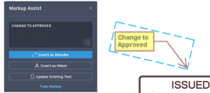
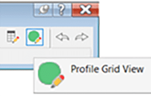
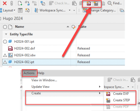
    On demand function will appear into the standard Vault Toolbar or also into the action menu

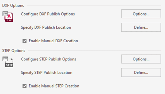
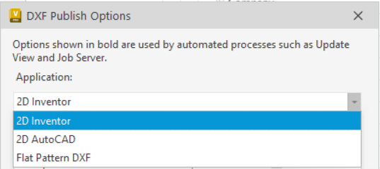
    DXF Options is available for 3 file types, 2D Inventor, 2D Autocad and Inventor 3D Flat pattern.

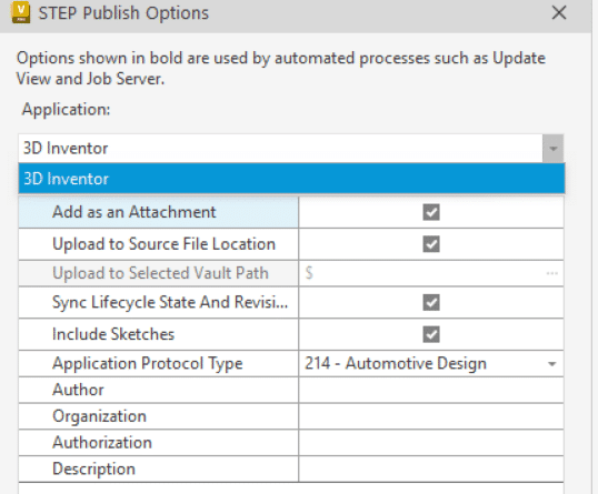
    STEP file option is only for Inventor .IPT and .IAM files.

    As the actual PDF option, you can specify publish options inside or outside the Vault. But take note that for the DXF Flat pattern, it’s impossible to specify a custom .ini file to generate the DXF with your custom configuration! We expect that this functionality will be added in a next available service pack or a possible workflow to modify the generic setup. I will keep you updated with another post when a solution will be available.

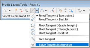
    For Lifecycle change state options you will find these options into the transition action Tab and the three small dots on the “Synchronize properties and update the selected file types using the Job Server”.

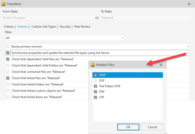
    Take note that if you choose the two DXF options you will have by default two .DXF files. By default the Vault naming rules are the “filename + actual file extension + .dxf”.

    Ex: if you have a file name as part 123.ipt with drawing 123.idw you will have 123.ipt.dxf and 123.idw.dxf.

    If you prefer to don’t have the original file extension into your .dxf, please don’t add two DXF options in same time.


    Now, how to change the DXF or STEP file naming default?

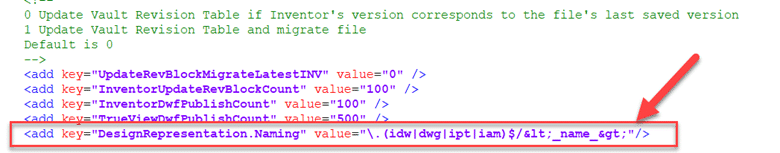
    As the actual PDF, you simply need to modify or add this following line into the JobProcessor.exe.config file.

    1.1)    <add key=”DesignRepresentation.Naming” value=”\.(idw|dwg|ipt|iam)$/&lt;_name_&gt;”/>

    I suggest this link to see more about file naming options: https://help.autodesk.com/view/VAULT/2024/ENU/?guid=GUID-F05BFEAF-A362-4070-BBA6-F3A74602967E

    The suggested line in 1.1 will create STEP, DXF & PDF without file extension. And it will be applied for .ipt, .iam, .dwf and .idw files.

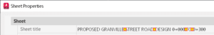
    It’s why you see in yellow below the value added in the option (not mentioned into the Autodesk help)
    value=”\.(idw|dwg|ipt|iam)$/&lt;_name_&gt;”/>

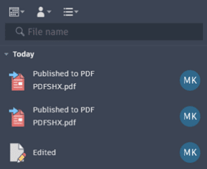
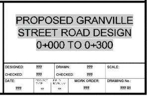
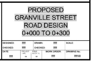
    Example of the result:

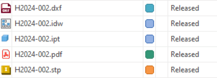
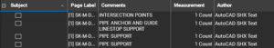
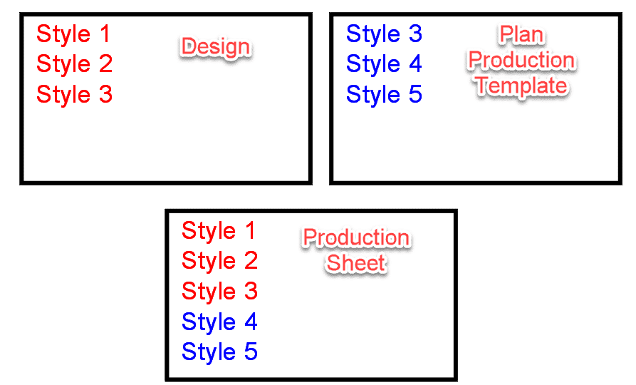
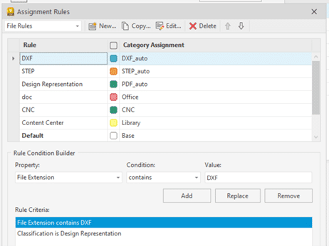
    All files generated by the job processor (PDF, DXF & STEP) are Design Representation and you can easily assign specific categories to them.

    All these files have a specific property because they are created by the Job Processor. The property is “Classification” and type is “Design Representation”. So if you add this into your rules and the file extension, you will be able to automate other category for STEP, DXF or PDF not generated with the job processor.

    Enjoy the new tool and see more info into the Vault 2024 help!

    Hugo Trepanier

    AutoCAD Resources: In the Autodesk Cloud

    If you customize AutoCAD across your design team and you use the Autodesk Construction Cloud (ACC), read on…

    I’ll define AutoCAD resources as files that AutoCAD uses to support design content. Here are several common file types that are customized.

    • Plot Style Tables (CTB/STB)
    • Fonts (SHX)
    • Printer Files (PC3/PMP)
    • User Interface (CUIX)
    • Linetypes (LIN)
    • Tool Palettes

    Many organizations store these files in a folder on a network-shared folder and point the users’ AutoCAD settings to this folder. This is good since there is a single location (single source of truth) for these files. When a CAD Manager updates are adds a file, users will instantly have access to it. Some firms have experienced performance degradation with this method.

    Some organizations copy these resource files to the users’ computers and use synchronization software to manage changes to them. This can be good for AutoCAD performance since the files are stored on their physical computer and not across the network. Files typically do not syn until the computer has been restarted, however.

    With the Autodesk Cloud, we can have the best of both worlds. Install Autodesk Desktop Connector (ADC) v16 or later to make for the best experience. I’ll describe exactly why later in this article.

    1. Create a new ACC project and invite your users to it. I named mine CAD Resources and I created subfolders for each data type. Copy your resources to the appropriate folders in the cloud.

    2. In the Desktop Connector on each user’s computer, ensure that this project is visible.


    3. Also on each user’s computer, turn on this option for the resources folder. This is what ADC v16 is for. In v15, this was not an option. It is critical that the files physically reside on the user’s computers when AutoCAD is run. This setting ensures that.

    4. Lastly, configure your AutoCAD product’s settings (Options) to point to these location.

    Stay tuned for the next article where printing with the Sheet Set Manager for Web uses CTB files stored in this same CAD Resources project.

    To learn more about AutoCAD or the Autodesk Construction Cloud (ACC), feel free to  contact us and one of our representatives will reach out to you shortly.

    Sheet Set Manager for Web: Printing in the Cloud

    This is a follow-up to my previous article discussing using ACC for the storage of AutoCAD Resource files. If you’re using the Autodesk Construction Cloud (ACC) and publishing using the Sheet Set Manager (SSM), read on…

    A little history first. The Sheet Set Manager has been available for many years, and it solves many AutoCAD organizations and efficiency problems. When Autodesk Docs and ACC were made available, and users stored their files in the cloud, they experienced significant issues with the good-old SSM. This document outlines the issues and their solutions.

    Then we got the SSM for Web: a new cloud-based version of the SSM. At first, it was limited in what it could do, but with the latest version for AutoCAD 2023, it is much more robust.

    Enough about history, how does the SSM for Web publish? Here is the SSM for Web with 4 sheets. Note the area surrounded in red, the Support file location. I have set this to a separate ACC project named CAD Resources. It has a sub folder that contains CTB files.

    When you publish using the SSM, the publish action occurs online, not locally on a user’s computer. It’s not even publishing in the background. It just happens in the cloud. Understandably, your CTB files, and any other potential files AutoCAD needs when printing, must reside in the cloud and the SSM support location must be set to this folder.

    Warning: even if your installation of AutoCAD uses a non-cloud CTB file, when publishing from the SSM for Web, it WILL use the one in the cloud. You MUST have a CTB file in the cloud.

    Pro tip: Give the system plenty of time to synchronize changes to the CTB. Like, maybe 10-15 minutes. Do not expect changes to be as fast as drawing edits. Restarting AutoCAD after editing the CTB seems to help.

    To learn more about the Autodesk Construction Cloud (ACC), feel free to contact us and one of our representatives will reach out to you shortly.

    AutoCAD 2024

    Well, it’s that time of year again when Autodesk bestows us with the latest release of their flagship drafting application. Click here for Autodesk’s documentation. Read on to see which features speak to this blogger.

    File Format

    This is probably the most-asked question, and I’m happy to say that there is yet again, no format change. We are still on the 2018 format. Happy news for everyone!

    Activity Insights

    Changes or actions made to your drawings are logged in a database so users can verify elements of a drawing’s history. One interesting thing here is that one can see that their drawing has been XREFd to another drawing.

    Pro tip: There is an option in AutoCAD to specify where to place the database; if you’re in a corporate environment set this to a shared folder so edits are tracked for all users that edit the file.

    Smart Blocks

    Place blocks with ease. Machine learning is used to learn how you place blocks. Blocks can be placed automatically in a room corner, for example. Replace blocks with another block and the software will hold rotation and scale values. Replacement blocks are suggested; AutoCAD uses machine learning to suggest blocks similar to the ones being replaced.

    Markup Assist

    This feature has been enhanced this year to automatically align a markup file (PDF, JPG, PNG, etc.). Also, AutoCAD text can be replaced with markup text as well as fading markups to help track which ones have been addressed by the user.

    PDFSHX

    This is a setting in AutoCAD for users who still use SHX fonts such as ROMANS or SIMPLEX. Historically, these old fonts have proven problematic with PDF viewers like Bluebeam Revu. They bloated PDF files and users could not search for text when SHX fonts were in use. PDFSHX is not a new setting. In previous releases, when turned on, it allowed text to be searched even if SHX fonts were in use. Each text object was a unique comment or markup in the PDF editor. Thousands of “markups” could be created, bloating the PDF. This setting now has 3 possible values:

    • 0 = off
    • 1 = the previous behavior
    • 2 = the new behavior. PLEASE use this one. Text is stored as “hidden” comments AND nothing special must happen in the PDF to be able to search. Is the PDF still bloated? In my limited testing, yes, the PDF is bigger when this is set to 1 vs. 2.

    See the Author in the PDF “markups”? (this is the old behavior = yuck!)

    AutoLISP

    LSP files can be loaded and run within AutoCAD LT. There are certain limitations; see the documentation for the list of what is and is not possible. This does not work with AutoCAD for Mac, only Windows.


    To learn more about AutoCAD, feel free to  contact us and one of our representatives will reach out to you shortly.

    Sheet Set Manager: Multi-Line Titles

    If:

    • Your sheet titles are too long for a single line in your title block and,
    • You use the sheet set manager to control these titles and,
    • You would like to control where the line break occurs…

    Read on…

    Multi-line attributes are handy when the information needs to wrap to additional lines. This attribute can contain a sheet set field which displays the title of the sheet. The attribute width can be adjusted to any width and the text will wrap automatically.

    But what if we don’t like how the text is wrapped? Maybe we want to dictate our own line returns. Suppose we want this instead.

    It is totally possible, though not at all intuitive. Here are the steps:

    1) Make the multi-line attribute width very narrow, like 1mm.

    2) Edit the title property in the sheet set manager.

    3) Place a space where you wish the line break to happen and place a non-breaking space where you actually want spaces. The red and yellow icons below indicate where the non-breaking spaces are.

    You see, when there are non-breaking spaces, the text following it is forced to reside on the same line.

    Alt+0160 to get a non-breaking space, hold down the ALT button while entering 0160 on your keyboard number pad. You MUST have a number pad; this will not work with the numbers on top of your keyboard.

    Civil 3D: Scary Halloween Tidbit

    Many AutoCAD users know about the OVERKILL command, which is used to delete duplicate objects. There are settings which define what exactly constitutes a duplicate object. Same geometry, layer, colour, etc.

    Many Civil 3D users configure pipe networks in their templates, so users need not create them on the fly when it’s time.

    Here is the scary bit. Please, DO NOT use the overkill command when there are empty pipe networks in a drawing. If you do, your pipe networks will be…

    Seriously, they will be deleted unceremoniously. Don’t do this!

    Civil 3D 2023.1 Update

    Autodesk has released the Civil 3D 2023.1 update.  Use the Desktop App to install it or download it from your Autodesk AccountClick here to find out what’s new and what’s been fixed. Please note that you must first install the AutoCAD 2023.1 update.

    Most of the enhancements are centered around Autodesk Docs features.


    Fixed Issues

    Autodesk Trust Center

    For the latest information regarding the security fixes in this Update, refer to the Security Advisory:

    ADSK-SA-2022-0014

    ADSK-SA-2022-0016

    Problems Reported Through the Customer Error Reporting Utility

    As a result of the detailed information that we received from customers who used the Customer Error Reporting Utility, we were able to identify and fix several defects including the following:

    Graphics

    Occasional crashes when selecting some objects with BLEND commands under “Shaded (Fast)” visual style.

    Occasional crashes when switching to “Shaded (Fast)” visual style in some drawings.

    Occasional crashes when launching AutoCAD on some machines with few specific graphic drivers.

    General

    Occasional crashes when opening and then saving some specific drawings.

    Occasional crashes when using PASTESPEC to copy Microsof Excel table into the drawing.

    General Update Content

    The following defects have been fixed:

    Display

    When you turn on/off layers, the objects in the drawing are reflected correctly.

    The dimension preview now displays under “Shaded (Fast)” visual style.

    The 3D objects can rotate correctly on the expected location when orbiting through 3D gizmo under “Shaded (Fast)” visual style.

    Bold and italic formatting in MTEXT now works as expected under “Shaded (Fast)” visual style.

    Markup Import and Markup Assist

    The Markup Assist boundary displays correctly when holding the wheel to pan on one of the locked viewports.

    The Markup geometry keeps the uneditable status after using the TRACEBACK command.

    Pressing the Esc key now cancels the Markup Import process.

    The imported images keep the embedding status after the Markup import is completed.

    Performance

    Improved performance when plotting a file with the raster image pasted and setting “Background Transparency” to Yes.

    Improved performance when orbiting the drawing containing multiple leaders with SHIFT+middle mouse button under “Shaded (Fast)” visual style.

    Improved performance on Hatch pattern previews on the ribbon drop-down list.

    Trace

    The Markup entity can be recognized successfully after undoing the new trace creation.

    The “Trace – Name Already Exists” message now displays when there is a duplicate trace name.

    Sheet Set Manager with Autodesk Docs

    The Edit button on the Sheet Set Manager for Web palette automatically adapts the palette width.

    The expand status on Sheet Set Manager for Web palette is now kept when switching the color theme in AutoCAD.

    The cloud DST file is now recorded on the Recent documents list.

    User Interface

    Drop-down lists now display clearly in certain dialog boxes in Windows 11.

    The QVLAYOUT thumbnail previews can be hidden automatically when selecting one of the layout previews.

    The underscore in the action macro name on the Action Recorder panel now shows in the drop-down list.

    The Close button now displays completely on the top-right side of the Start tab.

    The scroll bar and icons now show correctly in the Recent tab when setting display scale to certain values.

    An error message has been fixed when pressing the Esc key to close “Sort” pop-up list on the Start tab.

    Any layer can now be dragged into a Layer group filter in Windows 11.

    General

    TRIM and HATCH now recognize the edges of Civil 3D objects.

    All copied dimensions now appear at their specified locations correctly when associative dimension is copied multiple times.

    OLE objects now display correctly in Windows 11.

    Commands can now be entered immediately after switching layouts between multiple layouts.

    The renaming function in the Sheet View Category on the Sheet Set Manager is now implemented successfully.

    The Explode option on the Blocks palette is now retained after relaunching AutoCAD.

    The OVERKILL command behavior is now consistent with legacy products.

    Some specific STEP files are now imported correctly into AutoCAD.

    MLEADER objects converted from multiple text objects can now be set to a correct Z value.


    Parent page: AutoCAD Updates

    AutoCAD 2023.1 Update

    Autodesk has released the 2023.1 updates.  Use the Desktop App to install it or download it from your Autodesk AccountClick here to find out what’s new.  Additionally, the 2023.0.1 update is also available.

    This release includes new and updated features, performance enhancements, and fixes for Autodesk® Civil 3D® 2023. It is strongly recommended that you read this entire document before installing.

    Note: AutoCAD 2023 Update 1 must be installed before Civil 3D 2023 Update 1. AutoCAD 2023 Update 1 cannot be uninstalled independently. To remove the update, you must reinstall Civil 2023.0.

    New Features

    Find out about the new and improved features in the Autodesk Civil 3D 2023.1 release.

    Fixed Issues

    Find out what issues have been fixed in Autodesk Civil 3D 2023.1.

    Known Issues

    Find out about known issues in Autodesk Civil 3D 2023.1.

    Installation

    Detailed installation information can be found in the Autodesk Civil 3D installation help topics.

    • It is recommended that you first install all Microsoft® Windows® updates prior to installing Autodesk Civil 3D 2023.1.
    • Please close all applications prior to installing Autodesk Civil 3D 2023.1.
    • Autodesk Civil 3D 2023.1 can be installed side-by-side with prior versions of Autodesk Civil 3D.
    • If your team works in a multi-seat stand-alone environment, you can repeat this basic installation process for each computer seat. Alternatively, an administrator can create a deployment.

    Civil 3D: Plan Production Styles

    Do you use Civil 3D’s plan production tools?  Do you wonder where the styles come from, the design file, the production template?  Read on to find out.

    If you’re not familiar with Civil 3D’s plan production tools, here are the Cole’s notes.

    • Paper space layouts complete with your company’s title block and plan and/or profile viewports are created automatically along the entire length of a selected alignment.
    • A plan production template must be selected which contains a layout configured for use with this feature.
    • These layouts can be created in one of three places:
      • In the current drawing.
      • In new drawings, one layout per drawing.
      • All layouts in a single new drawing.

    When the option to create layouts in a single new drawing or multiple drawings is chosen, there are three files in play.

    • The design file
    • The selected plan production template
    • The production sheet file the tool creates

    Both the design file and the selected template can contain styles.  They could be the same styles, or they may be different.  When creating the new drawings, which of these two files does Civil 3D use as the template: the starting point?  Where do the styles and settings come from?

    The answer is both, sort of.  Here is what happens:

    1. Civil 3D uses the design file as the template.  All styles and settings come from this file.
    2. Any styles present in the production template are then duplicated into the new production sheet drawing.
    3. If there are any styles in the production template that are the same name as the design file, they are ignored.  The design file styles are maintained.

    Note that Style 3 is present in the Design and Template files.  In the Sheet file, Style 3 is the same as the Design file.

    Civil 3D: Profile Grade Intersections

    The goal in this example is to design the profile where each grade is an even number.  It’s not as obvious as you might think.  Thanks to my colleagues Dave Hill and Jae Kwon for pointing out the proper tool.

    Read on to learn more…

    Begin by modelling the first 2 segments.  I’ll assume you know the best tools for this, but I’ll give you a hint.  Use the Grid View; it’s your friend here.


    To model the last 5% grade is not entirely obvious.  Yes, a 5% tangent can be drawn from the end of the 1% grade, but it doesn’t end in the right place.

    We sort of want to draw backwards from the end of the red profile and then extend the 1% grade.

    Use this tool and follow the prompts.  First select the 1% grade, then pick Station and Elevation and the tie-in point.  Then enter the grade, in this case -5% (the grade from the intersected PVI).


    C’est voilà.