• Bluebeam Compare Documents vs. Overlay Pages

    This story was originally published by on the Bluebeam Blog.

    Discover how Compare Documents and Overlay Pages by Bluebeam transforms managing documents with precision and visual clarity.

    In the world of digital document management in the architectural, engineering and construction (AEC) industry, precision and efficiency are paramount. Professionals across the industry rely on tools that streamline their workflows and enhance collaboration.

    Bluebeam offers two powerful features—Compare Documents and Overlay Pages—each designed to serve specific purposes. In this article, we’ll delve into the intricacies of these tools to help users make informed decisions on which to use, and when.

    Compare Documents: A Closer Look

    Bluebeam’s Compare Documents feature is a robust tool designed to highlight the differences between two versions of a document. This can be especially invaluable in scenarios where document revisions are frequent.

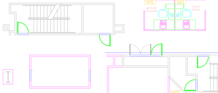
    When a user initiates the Compare Documents function, Bluebeam Revu meticulously analyzes the content of the selected documents and generates a comprehensive report highlighting any discrepancies. This includes additions, deletions and modifications made between the two versions. The software employs a color-coded system, making it easy for users to identify changes at a glance. Typically, additions are highlighted in green, deletions in red and modifications in blue; for Compare Documents, cloud markups are added around the differences.

    The utility of Compare Documents extends beyond textual content. It can also identify changes in graphical elements, providing a holistic overview of alterations in the document. This feature not only accelerates the review process but also minimizes the risk of oversight.

    Overlay Pages: Unveiling the Integration

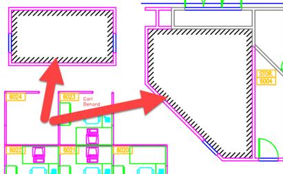
    Overlay Pages is another powerful feature within Bluebeam’s arsenal, designed to facilitate precise document comparisons and analysis. Unlike Compare Documents, Overlay Pages allows users to superimpose two versions of a document on top of each other, providing a visual representation of their differences.

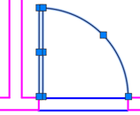
    This feature is particularly beneficial when dealing with architectural plans or any document where graphical elements are of utmost importance. By overlaying the pages, users can visually assess discrepancies in the placement of elements, ensuring that the design conforms to specifications. This method of visual inspection can be more intuitive for certain types of documents, providing a complementary approach to the text-centric Compare Documents feature.

    Integration for Comprehensive Analysis

    While Compare Documents and Overlay Pages serve distinct purposes, their integration can offer a comprehensive solution for users seeking an exhaustive analysis of document revisions.

    By first employing Compare Documents to identify textual changes, users can then turn to Overlay Pages to visually inspect the graphical alterations. This combined approach ensures a thorough examination of both textual and visual elements, leaving no room for oversight. The seamless integration of these features in Bluebeam empowers users to achieve meticulous precision in their document review processes.

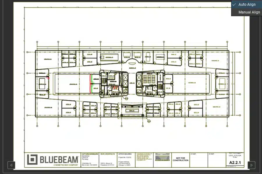
    Auto Align Makes Compare Documents and Overlay Pages Even Better

    Released in April 2024, Revu 21.1 gives Compare Documents and Overlay Pages an overhaul. Not only has the user interface been greatly improved for easier navigation and previews of the results, but Bluebeam has also added AI. Auto Align is an AI-enabled capability allowing for documents and pages to align automatically.

    Auto Align reduces the tedious, error-prone steps of manually aligning three points on each drawing revision, so users can understand the differences between them faster. Bluebeam customers currently use the Overlay and Compare features more than 5 million times a year. With the Auto Align option, users can now understand the differences in their documents and pages up to 80% faster.

    The Future of Manufacturing: iLogic & CPQ Software Unleashed 

    The Future of Manufacturing: iLogic & CPQ Software Unleashed 

    In the ever-changing world of manufacturing, the emergence of iLogic-based CPQ (Configure, Price, Quote) technologies, such as SolidCAD’s Variant, represents a significant turning point. These innovations are leading us into a new era characterized by remarkable efficiency and unparalleled customization. This blog will look into how the combination of iLogic’s rule-based engineering and the versatile capabilities of CPQ systems is transforming industry standards.

    We’ll explore the significant benefits that iLogic-based CPQ solutions bring to the table, including streamlined operations, improved product customization, and enhanced operational efficiency. By examining these cutting-edge technologies, we’ll show how manufacturers are now better equipped to tackle the challenges of today’s complex markets with increased agility and accuracy, thereby achieving higher levels of customer satisfaction.

    Come with us to explore the endless possibilities that new ideas are bringing to the manufacturing industry. This is leading to a future with no limits, only what we can imagine.

    iLogic: The Driving Force Behind Automated Design 

    iLogic, a key component of Autodesk Inventor, is revolutionizing the world of design automation. By allowing users to create rules that automate and control design processes, iLogic significantly enhances engineering efficiency. This tool is not just about simplifying tasks; it’s about redefining how we approach design in the manufacturing software landscape. 

    Decoding CPQ: More Than Just a Tool 

    CPQ (Configure, Price, Quote) software streamlines the way businesses sell complex, configurable products. When integrated with Inventor models, this software empowers sales teams, dealers, and even customers to quickly generate accurate quotes, ensuring manufacturing efficiency and optimizing sales processes. CPQ is more than a tool; it’s a game-changer in the business solutions arena.  

    Real-World Applications of CPQ Software 

    The practical applications of CPQ software are vast and varied. From small businesses to large corporations, the implementation of CPQ software has led to significant workflow improvements and sales acceleration. Check out mk North America’s success story to see how CPQ made a tangible difference. 

    The Evolution of Manufacturing Technologies 

    As we look to the future, it’s clear that technologies like Variant are not just shaping current manufacturing processes but is also paving the way for a more efficient, productive, and innovative future in the manufacturing sector. Subscribe to our blog channel to stay tuned as we continue to explore these exciting developments in the world of manufacturing technology. To learn more about Variant CPQ, try it for yourself on our website, or contact us today at variant@solidcad.ca 

    Civil 3D 2025

    Well, it’s that time of year again when Autodesk bestows us with the latest release of their flagship Civil Design application. Read on to see which features speak to this blogger.

    File Format

    This is probably the most-asked question, and I’m happy to say that there is yet again, no format change. We are still on the 2018 format. Good news for everyone!

    Performance

    Performance has yet again been significantly improved across the board in Civil 3D 2025.0.

    Corridors

    There is a new corridor creation dialog box that will allow for more efficient creation of corridor with multiple baselines using alignments and feature lines.

    Civil 3D 2025

    Civil 3D 2025Civil 3D 2025

    Coordinate Systems

    New horizontal coordinate systems have been provided.

    A new vertical coordinate system workflow exists to specify the survey datum. The new command is GEOCSASSIGN.

    Another new system variable named, ENABLEVCSSUPPORT, exists for DEM/GeoTIF files.

    Civil 3D 2025

    Surfaces

    Level of detail tools are intended to increase performance by reducing the amount of data displayed on the screen. Note that in 2025.0 ,two previous commands have been removed: LEVELOFDETAIL and LEVELOFDETAILOFF. These are replaced by object-based settings.

    Civil 3D 2025Civil 3D 2025

    For any questions reach out to your sales rep or contact us at info@solidcad.ca

    6 Bluebeam Features Perfect for Steel Professionals

    This story was originally published by on the Bluebeam Blog.

    Bluebeam has many capabilities that are ideal for the steel industry to get bids done faster and more efficiently.

    Steel is an essential building material. The people who work to procure and supply steel for construction projects spend a lot of time in the pre-construction phase tabulating the amount of the material the project will require based off plan documents, along with the estimated cost.

    Historically, steel professionals were left to do this work the old-fashioned way—off paper plans, with highlighters, pen and a host of other analog tools to calculate a project’s needed supply and estimated costs. Thanks to the advent of digital tools, that is no longer the case.

    Tools like Bluebeam now allow steel professionals the opportunity to reduce the time it takes to complete project bids with analog workflows from weeks down to a matter of days, giving them a tremendous competitive advantage.

    “The biggest advantage of using Bluebeam for steel is in the pre-construction phase of a project,” said Charles Todd, a Bluebeam industry consultant who previously spent several years working in steel fabrication. “Doing it the old, paper-based way is like doing twice the work.”

    Here are six features in Bluebeam that make it essential for the steel industry: 

    Markup List

    The Markup List adopts a table format, where each row corresponds to a markup added to an active PDF, and each column displays specific information about the markup.

    Selecting a row prompts the PDF view in the workspace to jump to the associated markup location, facilitating navigation through markups using the UP ARROW and DOWN ARROW keys.

    For steel professionals, this tool is paramount for organizing markups for quick and easy reference, especially for pre-construction estimations that go a long way toward winning bids. The list can also be exported in various document types, allowing for quick record-keeping and information sharing among colleagues.

    Measure

    The Measure tool facilitates the creation of measurements in various modes. These measurements can either persist as markups, helping in processing and summarization through the Markup List, particularly valuable for estimation and takeoffs. Alternatively, they can be temporary, providing a swift means to measure without generating a visual record on the PDF.

    Measuring and creating cost estimates for steel beams are critical in the pre-construction estimation process. Not only can steel professionals find massive time savings in using the measurement tool, but customization capability also allows users to associate accurate weights for steel quantities. This can help steel workers calculate accurate materials costs with the click of a button.

    Count

    The Count tool generates a markup with every mouse click, linking a cumulative count with each placed markup. It resembles Sequences in the Tool Chest, differing in that it introduces a preconfigured (typically less conspicuous) or personalized symbol onto the PDF. Moreover, the Count tool maintains an ongoing tally, either per page or Space, for each item counted. In contrast, Sequences count on the PDF without maintaining a continuous tally, treating each markup independently and refraining from grouping them in the Markup List.

    For drawings that need to identify and count the specific number of steel beams, for instance, this tool can be incredibly helpful. Simply clicking each beam or other building element in a digital plan document allows the tool to automatically tally a total number.

    Tool Sets

    Tool Sets in Bluebeam can be generated and exchanged seamlessly among various users. These sets are versatile, allowing for local saving, network sharing or exportation to other users. Sharing Tool Sets proves invaluable for establishing consistent markups tailored to diverse projects, job roles, clients and beyond. Effectively managing these Tool Sets is a crucial aspect of maximizing the utility of Bluebeam.

    Steel fabricators can establish Custom Tool Sets specific for their needs during the pre-construction estimation process, allowing for a cleaner and more efficient workflow for creating job-winning bids faster.

    Profiles

    Profiles offer a convenient method to save preferred toolbars, menus and display settings, ensuring that the most essential tools are easily accessible every time Bluebeam opens.

    What’s more, as with Tool Sets, Profiles can be customized for steel workers’ specific needs. Doing so allows workers maximum levels of efficiency for all specific steel-industry uses of the software, such that workers don’t have to toggle between unfamiliar or unnecessary tools to get the job done.

    Integration with External Digital Tools

    Finally, many of these tools in Bluebeam can be integrated with other essential steel industry digital tools. For example, exporting the Markup List to a Microsoft Excel file is one way to then upload that information into another piece of complementary software. Such seamless integration allows steel workers to complete complex estimation tasks in a fraction of the time that it would take with old, analog processes. What’s more, calculations are more likely to be accurate, leading to fewer errors or costly and time-consuming rework.

    Bluebeam is an essential tool for anyone in the architecture, engineering and construction (AEC) industry, but it is especially useful for those working in steel.

    AutoCAD 2025

    Well, it’s that time of year again when Autodesk bestows us with the latest release of their flagship drafting application. Here is the Official Documentation. Read on to see which features speak to this blogger.

    File Format

    This is probably the most-asked question, and I’m happy to say that there is yet again, no format change. We are still on the 2018 format. Good news for everyone!

    Activity Insights

    More actions are being logged into the Insights.

    If you use the DWG History tools, these have been merged with Activity Insights. Note: the history is now only available within the Insights palette. The DWGHISTORY command no longer exists, though the functionality is still there.

    AutoCAD 2025

    AutoCAD 2025

    Markups

    Markups from Autodesk Docs are now supported.

    Assigning specific annotation styles is now possible.

    Polygonal revision clouds are supported.

    Comments attached to markups are selectable.

    Hatch

    This one is pretty cool! Draw a new hatch object without creating or specifying a boundary. E.g. use the new hatch rectangle command to quickly create a hatch. Not limited to rectangles; any shape is possible.

    A new hatch path option is available. This creates a hatch of a specified width along a path, like a polyline.

    AutoCAD 2025

    Blocks

    AutoCAD can use machine learning to detect linework and convert that linework to a block. Imagine a drawing where all the door blocks were exploded. You would prefer that they had not been. Use the new command to identify those door lines and convert them to a block

    AutoCAD 2025      AutoCAD 2025

    ESRI Maps

    ESRI maps are now integrated into AutoCAD. Now, you can use five additional types of Esri maps to assign geographic location information to a drawing file.


    AutoCAD 2025

    AutoCAD 2025

    For any questions reach out to your sales rep or contact us at info@solidcad.ca

    Civil 3D: Object Names and Style Descriptions

    Does your company require the use of a specific naming convention for Civil 3D objects? Has it been difficult to adhere to that standard? If so, read on for some tips.

    When an object is created in Civil 3D, it requires a name. This is the naming convention for a new alignment using the out of the box Civil 3D drawing template. It will be named Alignment – (1), the next one will be Alignment t – (2), etc. This name is not very descriptive, and I hope you’re using something better than this already!

    Here is an example of a company’s strict naming convention.

    1234-C-Granville-ALG

    • 1234                     =             project number
    • C                            =             civil
    • Granville              =             road name
    • ALG                       =             alignment

    Users must refer to a naming standard, often a PDF document somewhere on the network, and this can take time. Under pressure, users sometimes skip the formalities and use a non-standard name. We must make it as easy and fast as possible for them.

    Why not embed this standard into the drawing template itself so users won’t need to open another file? Here is how this could be done directly in your Civil 3D drawing template. The users’ responsibilities would be to edit the mixed-caps data and leave the ALL CAPS data.

    Prompting the user with the information they need when they need it will help to ensure better efficiency and (potentially more important) reduce the chance that they use non-standard names. This can be done for all relevant Civil 3D objects in the Settings tab by:

    • Editing the Feature Settings for the object in question.

    • Configuring the name template.

    • Clearing any child overrides so all alignments get named properly regardless of the command used.


    While we’re on the subject, it can be beneficial to include a good description with styles so that users are prompted when or why to use a style. I try not to have make the description so long that my users need to scroll to see the entire thing. They won’t! Make it concise.

    REAL-LIFE SUCCESS STORIES WITH MERIDIAN

    In the ever-evolving landscape of engineering and asset management, organizations seek robust solutions to streamline their documentation processes. Accruent Meridian has emerged as a game-changer, empowering companies across various industries to efficiently manage their critical information. Let’s explore some real-life success stories where Meridian played a pivotal role:

    1. Energy sector: optimizing workflows

    THE CHALLENGE:

    A leading energy company faced challenges in maintaining accurate records for its vast network of power plants, substations, and transmission lines. Manual paper-based systems resulted in inefficiencies, data duplication, and compliance gaps.

    THE SOLUTION:

    The company implemented Meridian to centralize its engineering documents, including schematics, equipment manuals, and maintenance logs. With Meridian’s version control and access permissions, engineers could collaborate seamlessly. Integration with their Computerized Maintenance Management System (CMMS) ensured real-time updates.

    THE BENEFITS:

    • Reduced Downtime: Faster access to critical information minimized downtime during maintenance.
    • Compliance Assurance: Auditors praised the system’s transparency and adherence to industry standards.
    • Cost Savings: Elimination of paper-based processes led to significant cost savings.

    2. Manufacturing: accelerating product development

    THE CHALLENGE:

    A global manufacturing firm struggled with document version chaos. Engineers often worked with outdated drawings, leading to errors, rework, and delays in product development.

    THE SOLUTION:

    Meridian’s automated version control and revision tracking transformed their engineering change process. Integration with Computer-Aided Design (CAD) tools allowed seamless updates. Engineers could collaborate on designs in real time.

    THE BENEFITS:

    • Faster Time-to-Market: Streamlined processes reduced design iteration cycles.
    • Quality Improvements: Accurate, up-to-date drawings minimized errors.
    • Regulatory Compliance: Meridian ensured compliance with industry standards.

    3. Construction: managing complex projects

    THE CHALLENGE:

    A construction company faced information overload during large-scale projects. Managing blueprints, specifications, and vendor documentation became overwhelming.

    THE SOLUTION:

    Meridian’s centralized repository organized project documents. Role-based access control allowed stakeholders to access relevant information. Mobile access enabled field teams to retrieve data on-site.

    THE BENEFITS:

    • Project Efficiency: Quick access to project plans improved decision-making.
    • Risk Mitigation: Compliance tracking reduced legal risks.
    • Collaboration: Contractors, architects, and project managers collaborated seamlessly.

    4. Healthcare: ensuring regulatory compliance

    THE CHALLENGE:

    The hospital system struggled with maintaining accurate records for its medical equipment. Compliance audits were time-consuming and error prone.

    THE SOLUTION:

    Meridian’s robust metadata management allowed tagging equipment with critical details. Integration with the hospital’s Electronic Health Record (EHR) system ensured seamless data flow.

    THE BENEFITS:

    • JCAHO Compliance: Quick access to project plans improved decision-making.
    • Equipment Lifecycle Management: Compliance tracking reduced legal risks.
    • Cost Control: Contractors, architects, and project managers collaborated seamlessly.

    CONCLUSION:

    Accruent Meridian isn’t just software; it’s an enabler of efficiency, collaboration, and growth. These success stories demonstrate how organizations, regardless of their industry, can leverage Meridian to unlock measurable benefits. Whether it’s reducing downtime, improving compliance, or enhancing collaboration, Meridian continues to shape the future of engineering documentation management.

    Remember, success stories aren’t just about technology—they’re about the people who embrace it and drive positive change. So, consider Meridian as your partner in achieving excellence! To learn more contact us today  SolidCAD Meridian Team.

    The Role of PLM in Streamlining New Product Development

    Introduction: The Importance of NPI in Product Development

    In today’s fast-paced and competitive market, the ability to innovate and bring new products to market swiftly is not just an advantage; it’s a necessity for growth. For product and manufacturing managers, the pressure is on more than ever to not only keep up with the pace but to lead the charge.

    New Product Introduction (NPI) process is pivotal element that can spell the difference between success and failure for product launch. NPI is the comprehensive process of bringing a new product from concept to market, encompassing design, development, testing, and launch phases. As businesses strive to outperform competitors and satisfy ever-evolving customer demands, the role of NPI emerges as a critical process where efficiency, speed, and innovation converge. Yet, navigating the complexities of product development, from conceptualization to launch, poses a formidable challenge. This is where Product Lifecycle Management (PLM) steps in, transforming the NPI process from a daunting task into a streamlined, strategic asset that propels companies towards success.

    PLM’s Role in NPI

    Product Lifecycle Management (PLM) is managing the entire lifecycle of a product from inception, through engineering design and manufacture, to service and disposal, by integrating people, data, processes, and business systems. While NPI focuses specifically on the process of bringing a new product to market, PLM encompasses a broader strategy managing the entire lifecycle of a product, from initial concept through to its ultimate disposal, including the NPI phase.

    PLM in NPI

    Figure 1: PLM in NPI – The entire map is PLM, encompassing every aspect of a typical business’ processes. NPI is a component of PLM that is typically the starting point of your development of a new product or project.

    PLM serves as the backbone for NPI, providing a robust framework that revolutionizes how companies manage product data, foster cross-functional collaboration, and ensure compliance with industry standards as shown in Figure 1. By centralizing product information in PLM, it enables all stakeholders, from engineers to marketers, to access up-to-date data, ensuring that decision-making is based on the most current information. This centralizing of product information not only streamlines the NPI process but also significantly reduces errors and redundancies, accelerating the time-to-market.

    Furthermore, certain PLM software such as Autodesk’s Fusion 360 Manage, have collaborative tools that break down silos between departments, enhancing communication and coordination across various teams in your NPIs. These tools include task management, BOM management, automated notifications, Gantt charts to display project progress and more. This synergy is vital for aligning goals, refining product designs, and ensuring that every aspect of the product introduction is synchronized.

    Strategies for Effective NPI Using PLM

    Utilizing the NPI process in PLM is pivotal for companies aiming to streamline their product development and launch processes. To maximize the effectiveness of PLM, several best practices are essential. Firstly, establishing a centralized database for product information is critical. This repository becomes the single source of truth for all data related to the product, from initial design sketches to final specifications, ensuring consistency and accessibility across the organization.

    Integrating PLM with other enterprise systems, such as Enterprise Resource Planning (ERP) and Customer Relationship Management (CRM) systems, further enhances effective use of NPI. Such integration ensures seamless information flow across different business processes in their respective software solution, facilitating better decision-making and reducing time-to-market in your NPI process. For instance, ERP is typically used to manage supply chain. Thus, integrating PLM with ERP allows for real-time visibility into the supply chain, aiding in materials planning and financial forecasting and connecting it your product data such as the product BOM.

    To dive deeper into this, watch Autodesk’s webinar about utilizing PLM to bring your new products faster. The webinar explains how leveraging PLM software for project management and workflow automation is another best practice that can significantly impact the NPI process. This article by Autodesk further highlights the systems in PLM and briefly covers how NPI works alongside processes.

    Case Studies

    Reynaers Aluminium, a leading innovator in architectural solutions, demonstrates the remarkable benefits of integrating PLM into their New Product Introduction (NPI) processes. By adopting Fusion 360 Manage, Reynaers addressed critical challenges in product development, achieving remarkable outcomes. The customer story will go in depth of this transformation by adopting Fusion 360 Manage as their PLM solution and using it as a tool for various uses, including managing their projects with their product data.

    Conclusion

    Throughout this article, we’ve underscored the critical role of PLM in enhancing and streamlining NPI, from providing a centralized platform for managing product data to facilitating cross-functional collaboration with other business essential software such as ERP and CRM. The advent of PLM technology, particularly with the emergence of cloud-based solutions like Fusion 360 Manage, marks a significant evolution in the field. These modern PLM systems offer unprecedented flexibility and efficiency, enabling organizations to respond more dynamically to market demands and innovate at a faster pace.

    Civil 3D: 2024.3 Update

    Civil 3D 2024 has a new update: 2024.3. You can use Autodesk Access to install it or download it from your Autodesk page.

    Here are the notable enhancements.

    Civil 3D: 2024.3 Update

    • When creating a new corridor, expect to see this new dialog. It allows for the creation of multiple baselines right at the time of corridor creation. For large corridors, this could be a significant time saver.
    • In that same new dialog, feature lines can be more efficiently chosen by filtering based on criteria such as Name, Style, Layer, and Site.
    • Assign alternate assemblies in Corridor Properties for multiple baselines and regions simultaneously.

    Civil 3D: 2024.3 Update

    • The Dynamo Core has been updated to version 2.19. Note, that this can cause issues with Dynamo scripts created prior to 2.19…
      “if you have no nodes set as “Output”, nor a Slider or Boolean Input, it will never show your Inputs in the Dynamo Player.”
      “Adding a node as an Output will “solve” this issue”

    In the API, Added the ability to call the API to export C3D objects to the ArcGIS FileGeodatabase to automate workflows from C3D to ArcGIS.

    Can Climate Proofing Structures Help Reverse Climate Change?

    This story was originally published by on the Bluebeam Blog.

    With the built environment such a prominent source of carbon emissions, it is vital that the industry recognizes the urgent need to ‘climate proof’ homes and other built assets and infrastructure.

    Everyone is aware of the potentially catastrophic consequences of climate change. Climate change has been exacerbated by human activity, particularly since industrial activity increased dramatically in the 1800s. The burning of fossil fuels such as coal, oil and gas generates greenhouse gas emissions, effectively trapping the sun’s heat and raising temperatures around the world.

    Responding to the looming crisis, international governments have pledged to lower carbon emissions to reduce global warming. Only last month negotiators from dozens of countries agreed to shift away from fossil fuels at the COP 28 climate summit.

    Yet as the United Nations (UN) points out, rising temperatures are just the start.

    “The consequences of climate change now include, among others, intense droughts, water scarcity, severe fires, rising sea levels, flooding, melting polar ice, catastrophic storms and declining biodiversity,” it says.

    Eliminate carbon emissions from buildings

    The built environment is stepping up and playing its part in reducing carbon emissions. Since construction activity and building occupation accounts for around 39% of global carbon emissions, the pressure is on designers, developers, building owners and operators, and occupiers to make buildings greener.

    There is much work to do. A report called “UK Housing: Fit for the Future?,” published in 2019 by the UK government’s advisory Committee on Climate Change (CCC), argued that the UK’s legally binding climate change targets would not be met “without the near-complete elimination of greenhouse gas emissions from UK buildings.”

    The CCC’s report noted that efforts to reduce emissions from the UK’s 28 million or so homes had stalled, while domestic energy use—which accounted for 14% of total UK emissions—had increased. Worryingly, efforts to adapt the UK’s housing stock to the impacts of the changing climate—known as climate proofing—were “lagging far behind what is needed to keep us safe and comfortable, even as … climate change risks grow.”

    So how can the UK’s building stock, and particularly homes, be climate proofed?

    There are two approaches: First, when building new, do so to exacting standards that lower their environmental impact; second, retrofit existing buildings with materials and technologies to the same end.

    Build in weather resistance

    The UN’s Environment Programme (UNEP) says it is possible to build in resistance to heatwaves, extreme cold, cyclones and strong winds, coastal flooding and drought with a variety of construction strategies.

    “Structural designs can help reduce heat inside buildings,” the UNEP says. “In Vietnam, traditional housing designs such as the optimum orientation of buildings, high-rise rooms and large openings improve ventilation.”

    “Walls of concrete, stone or other heavy material that capture solar heat are used in China, Chile and Egypt. Green roofs and reflective surfaces can also reduce temperatures in and around buildings.”

    The UNEP says that adapting to cold and temperate climates “requires capturing heat and minimizing heat loss. Insulations in roofs, walls, ceilings and double-glazed windows help to minimize heat loss and lead to more energy-efficient buildings.”

    To resist the effects of strong winds, homes could be built in circular shapes, while strong connections between foundations and the roof are critical to building wind-resilient houses.

    Homes built in areas at risk of flooding could be positioned on pillars to allow floodwater to flow underneath, the UNEP suggests, while those in drought-affected regions could feature rainwater harvesting and recharge systems that capture water on the roofs of buildings.

    Passivhaus technology

    Companies have been working on climate-proof building concepts for years. Perhaps the most familiar example is the Passivhaus program. Developed in Germany in the late 1990s, key features of a Passivhaus are lots of insulation and airtightness, minimal thermal bridging, optimization of passive solar gain, mechanical ventilation with heat recovery and a simple, compact shape.

    According to the International Passive House Association, which promotes the Passivhouse Standard, along with “a greater public understanding of highly energy-efficient buildings,” such homes need just 10% of the energy used by typical Central European buildings.

    A disadvantage, at least in the short term, is that a Passivhaus costs around 8% more upfront to build, says the IPHA. But a house built this way eventually uses much less energy than a conventional new home, meaning over time this kind of outlay will be recouped; plus, there’s the improved comfort and structural performance to consider.

    We understand the sort of elements that should go into a newly built home. Let’s assume that new UK homes are being consistently built to high climate change-resistant standards and housebuilders lay claim to buyers making significant energy savings when acquiring “new.” The next question is what to do about existing homes?

    Given the age of most of the UK’s existing housing stock, this is an issue that needs tackling. More than half of the country’s homes were built before 1965, more than a third before 1945 and 20% prior to 1919. Just 7% has been delivered since 2000.

    Retrofitting homes—the costly solution

    Retrofitting has been put forward as the best solution. But given the number of households in the UK, around 28 million, the scale of the task is positively Herculean. The cost is not insignificant either.

    According to a study by the University of Nottingham, the cost of “deep retrofit”—effectively retrofitting a home to the highest levels of energy efficiency—is expected to average around £69,000, or $86,850, more than twice the government estimate for such work. So carrying out such retrofits on every older home in the country will come with a high cost.

    In addition, there is the time it will take to retrofit so many homes. But not doing anything isn’t an option, which the industry recognizes.

    Infrastructure is another area where climate proofing is vital so services can continue to function in the event of things like catastrophic flooding.

    According to the OECD, “ensuring that infrastructure is climate resilient will help to reduce direct losses and reduce the indirect costs of disruption,” which can result from the same factors that threaten the viability of so many homes across the country.