Register for Space Jam, the Matterport event series that showcases how our partners enhance Matterport offering and provide your customers with immersive experiences
Blog Source: Matterport
Architects, engineers, and construction professionals are quickly discovering the power of Matterport digital twins through every stage of their project cycles. Capturing and leveraging a digital twin ensures a solid project foundation, and as professionals across the AEC industry understand, a strong foundation is vital to the success of each and every project.
With that strong foundation, Matterport has continued to grow and evolve while staying laser (level) focused on the needs of end-users. We recently released a Notes feature, which is especially useful when several stakeholders, from a team of architects to a GC, are looking to make project updates or callouts. Notes supports a high level of collaboration across teams and projects, but is just the start. While Matterport supports notes, measurements, and even a scan-to-BIM file add-on for users, Platform Partners have taken digital twins to the next level.
Explore the offerings below and join us on February 24 for Space Jam, the Matterport Platform Partner Demo event. Learn how Partners can transform the way you work. Bring your questions because Partners will demo their products and stick around for live Q&A. Come ready to vote on your favorite presentation!
Do you need to censor something in your Matterport Tour, say a family photo, signage, license plates? Inside your Matterport Account, in the Edit Mode of a Showcase model, is the Blur Brush.
The Blur Brush is brand new and we couldn’t be more excited to show it off. Many of you have been patiently waiting for this tool to help boost privacy and control over what to hide in your Matterport spaces. This, however, is only the beginning. What Amir covers in this video is only version 1.0 of the Blur Brush. As the tool develops, we’ll be adding new videos and linking to them from here.
Register here: https://my.matterport.com/settings/account/manage
![]()
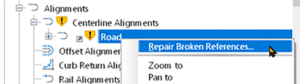
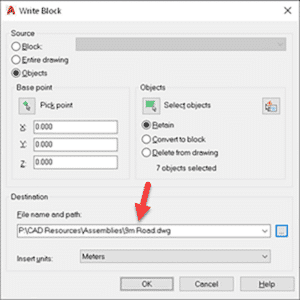
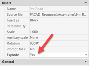
Beyond powerful tools, e-Building allows users to manage all their BIM models on a single platform and connect them to Matterport models. Upload Revit, SketchUp, Autocad and Inventor files as well as .IFC, .Stp files, point clouds and more. View, section, examine, share and associate files with a tag of the Matterport model and display them in the e-Building DataBox.
Use this solution for:
- Tag management
- Smart document management
- Model extension
- BIM Model management
![]()
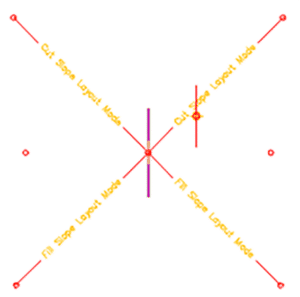
Nspect takes 3D data and creates layers on top that show what your team needs to see. This could be an inspection report, a quality control review, safety inspection, or a work plan for a site on how to repair and maintain a property. With their API, you can take this 3D data and place it in the tools you use every day, or keep it with them and have complete, instant access to the issues that your teams need to address.
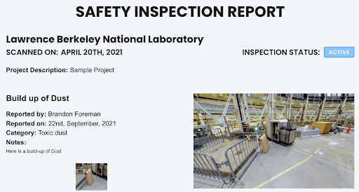
Use this solution for:
- Virtual site inspection
- Maintain safety requirements
Link to site: https://nspect.net/
![]()
RemSense has developed an industrial software package that uses Matterport as the image fabric that is overlaid with layers of information from client management systems. RemSense combines, adapts, modifies and implements existing and new technology to deliver solutions that solve complex engineering challenges.
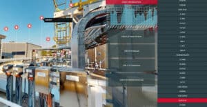
Use this solution for:
- Building your industrial metaverse
- Asset Augmented reality
- Asset management system visual navigation
- Virtual asset identification and audit
![]()
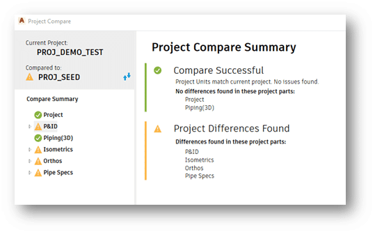
STAGES by SIMLAB is a tool used by all stakeholders to view, monitor, and compare building progress over time. Their goal is to create a living timeline of changes allowing users to view, collaborate, and solve issues throughout the full lifecycle of the property.
Use this solution to:
- Identify issues and collaborate on solutions
- Draw sketches in a 3D space
- Add notes to a project, including written, voice notes, video or files
Maybe you are new to Matterport, a long-time user, or find yourself someplace in between, no matter the case, we have partner offerings that will extend the value you provide to each and every project under your management. Matterport Platform Partners will help drive your business toward the next level of innovation. Join us on February 24, 2022 for Space Jam, where you will gain access to the solutions that will provide your customers and teams with transformative tools. Bring an open mind, and your questions, plus vote on your favorite presentation during this Matterport Partner AEC focused demo event.


")


_hr")
")