All these features are welcome, but two of them are great news to many, especially Civil 3D users. Specifically, the features related to point classification.
Notable changes are:
Scans are now imported and indexed in parallel, meaning faster imports.
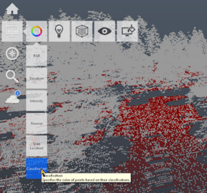
Clouds can be displayed using their classification if any exist in the imported file.
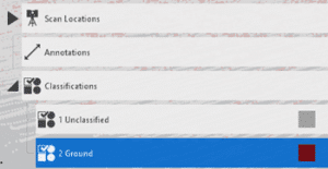
Classifications appear in the Project Explorer. These can be managed as needed. All points except, ground points, for example, can then be exported for use in other apps, like Civil 3D.
Unclassified points can be Automatically Classified. Scans must be structured, or the classification will fail.
Bluebeam’s dexterity as a construction technology makes it invaluable to the industry, but standardizing its tools and features to specific job roles or workflows makes it even more valuable.
Standardization is paramount in construction. Whether you’re a superintendent on a multibillion-dollar skyscraper project or an estimator on a mixed-use development, every industry player needs to abide by a set of standards to get the job done.
Using construction technology is no different. As digital collaboration tools continue to play an outsized role in the industry, it’s critical that those who are leading technology implementations customize the tools so workers can learn them quickly and apply them on the job effectively.
Perhaps no construction technology benefits more from standardization than Bluebeam. The tool’s pliability is one of its greatest strengths. Here’s how to apply standards to Bluebeam so you can get the most out of the technology.
Simplify what you see
Construction is a complex industry. Any given job may have more than 100 different types of roles, from the general contractor overseeing the production of a build, to the architects and engineers determining a project’s fine details, to the electrician carrying out those details.
Bluebeam is designed to help all of these people do their jobs better. Still, its capabilities are so robust that any first-time user might become overwhelmed. Therefore, it’s critical that, upon implementation, Bluebeam is customized with standards that are specific not just to each role but any particular workflows as well.
The best way to do this is to eliminate anything that’s unnecessary in Bluebeam’s interface. If you don’t need to create forms in Bluebeam, for example, scrap the icons and buttons to remove them from view. Repeat this with any other unneeded tools, panels or capabilities.
Create Custom Profiles, Tool Sets, Icons, Etc.
Revu, Bluebeam’s flagship PDF markup tool, has a seemingly endless amount of features. One way to completely customize Revu to better serve a job role or workflow is to save specific interface settings as a Profile, which can then be shared with other project colleagues.
Watch the video here https://youtu.be/RswYZRTXsVM
By creating custom Profiles, users can re-order and even turn off any of the interface’s panels and tools, ensuring that only the most used and relevant tools are in view. Users can do the same with the toolbars within Revu. Standardizing workspaces in Bluebeam with custom Profiles, and sharing those Profiles across teams, will go a long way toward simplifying the overall experience of using the technology.
Customization doesn’t stop with Profiles in Bluebeam. Markup tools—the symbols that are saved in the Tool Chest—can also be standardized as a custom tool set. Moreover, users can upload their own markup icons to standardize for use in a specific project or workflow.
Like with Profiles, implementation leaders should take advantage of such customization. From tool sets to specific markup icons, create a standardized experience in Bluebeam for your team that is as specific and simple as possible.
Review standards often
While establishing standards in Bluebeam is essential at the beginning of the tool’s implementation, it’s equally important that custom elements—from Profiles to tool sets—are reviewed and updated regularly.
Bluebeam is like a fine wine—it gets better with time. As knowledge of Bluebeam expands as people on your team continue to use it, it’s worthwhile to potentially integrate new tools and features as part of your customized standards.
Review these standards on an informal level every quarter, while larger, more robust standardization updates should happen once every six months to a year. Use these opportunities to gain feedback from users on which standards should be updated or eliminated.
The bottom line
Bluebeam’s versatility as a construction technology makes it invaluable to the industry. But with such flexibility comes the need to customize it for specific types of users and workflows. Failing to set standards when using Bluebeam—or any construction technology—risks slowing down the tool’s adoption and overall effectiveness over time.
A short article today. Click here for more the official documentation.
The Grading Optimization tool and Project Explorer are now available with a standalone license of Civil 3D. Previously, you needed to subscribe to the AEC Collection.
Starline Windows’ digital workflow on a connected cloud platform helps enable it to control its entire process, doing all its own assembly, manufacturing, construction, and installation. Courtesy of Starline Windows.
In Vancouver, Canada, window company Starline Windows was an early adopter of digital design and uses lean processes to deliver custom products.
The 2008 recession and COVID-19 pandemic both jumpstarted the company’s digital transformation to compete in a packed marketplace.
The result is a greener, more profitable, and more responsive business delivering more value to customers, partners, and employees.
Starline’s ongoing digital transformation has accelerated the design-to-delivery process by connecting data from various applications.
If buildings were bodies, the exterior would be the skin, blocking wind and rain while keeping everything inside warm and comfy. But in construction, vents, pipes, doors, and windows repeatedly puncture that outer layer. For a building to sustain the environment inside, those elements have to fit perfectly and seal seamlessly.
Defects that measure only millimeters become huge headaches if a window doesn’t quite meet spec. It may need to be trimmed onsite or reordered and replaced. Either way, it amounts to time lost and added expense. To get it right the first time, Vancouver, Canada–area window company Starline Windows has embraced digital design, making it the foundation for great industry relationships, profitable growth, and a more sustainable operating model. Starline has become a supplier of choice for many high-profile construction projects, collaborating effectively with internal and external partners.
Integration for Better Outcomes
Starline designs and manufactures architectural aluminum window systems for residential and commercial buildings. In business since the early 1970s, the company has delivered thousands of projects in its key California and Canadian (British Columbia and Alberta) markets. In fact, Starline Windows is responsible for making and installing the windows and doors in 25% of the high-rise buildings constructed during the past 50 years of the Vancouver, Canada, downtown core—the area most known for the city’s iconic skyline.
Starline’s array of window products includes punched, window-wall, curtain-wall, and balcony door. Unlike many manufacturing businesses that opted to outsource in the 1980s, Starline has stuck with a vertically integrated corporate structure in which most of its supply chain is company-owned, including state-of-the-art, fully automated manufacturing facilities.
“It’s a really special company,” says Catherine Walmsley, virtual construction manager at Starline. “We’re quite unique, and I think that comes down to not just what we do, but how we do it. We own our own supply chain. We do our own assembly and manufacturing. We have in-house IT support, and we do our own installation and construction.”
Starline Windows has made the windows and doors in about 25% of the high-rise buildings constructed in the past 50 years in Vancouver’s downtown core, such as the Modello (pictured) by Boffo Developments. Courtesy of Starline Windows.
When Starline takes on a job, “we work with our partners to meet their needs as well as our own,” Walmsley says. However, even with the level of control afforded by its integrated structure, the company still faces business challenges common to the envelope trades, including a lack of design collaboration with architects and contractors, poor visibility for field personnel when design revisions happen, and limited data sharing between the office and the field. A lack of cross-department collaboration can also get in the way of efficient logistics.
In a highly competitive market, working closely with project stakeholders to demonstrate value can be make-or-break. In its 2022 Pulse Report, Window + Door Magazine found that 62% of contractors were on the hunt for new window suppliers to protect the supply chain and keep up with customer requirements. Issues like flexibility, turnaround time, material availability, and pricing were among the top reasons cited for shopping around.
Traditional Structure, Modern Challenges
“When you’re working on a complicated project, you need to be able to work with others,” Walmsley says. “So it’s important for us to be able to understand the process as a whole.”
Improving end-to-end process clarity benefits every architecture, engineering, construction, and manufacturing business, but rising demand for custom designs makes this goal more challenging. As requirements become more tailored and less standard, better tracking and traceability across the product lifecycle is essential.
The efficiency of Starline Windows’ digital transformation helps make the company both more sustainable and more profitable. Courtesy of Starline Windows.
Working with architects closely at the outset and ensuring design commitments are being met from manufacturing to installation are necessary to meet custom requirements. The COVID-19 pandemic and its increase of remote working have compelled an industrywide rethink of how tighter collaboration and greater visibility can be delivered to clients.
But just as it decided early on to stick with a traditional business structure, Starline also became a digital early adopter. That’s put the company on the right footing to meet today’s challenges.
A Digital Early Adopter
“We do everything from design to manufacturing, installation, and even shipping,” Walmsley says. “That’s a lot of territory to cover, and anything you can do to virtualize construction information is a benefit.”
Starline recognized that issue as far back as the early 1980s, when it started the shift from paper drawings to computer assisted design (CAD).
Starline’s all-digital and cloud-connected design-to-delivery workflow makes it easier to deliver bespoke windows for large projects such as Civic Plaza, Surrey, British Columbia’s tallest building. Courtesy of Starline Windows.
“We were pretty early to embrace CAD,” Walmsley says. “We had an amazing IT guy, and once CAD went open source around 1985, we saw the opportunity to replace paper-based workflow and reuse all the data contained in hand drawings.”
Things really changed in the aftermath of the 2008 recession, when macro considerations forced the company to find new ways to rationalize costs and downsize—without sacrificing quality or delivery.
“We were always fans of lean operating principles, but after 2008, we had to go really lean and find ways to deliver the same number of projects with fewer people,” Walmsley says. “But we also had to enable the ones who stayed to work more efficiently. Our people in the field in the buildings were very attached to their pieces of paper, but when we put an iPad in their hands, it was a huge game-changer. Suddenly we could provide change paperwork on the fly without having to call FedEx and have a ream of paper delivered to the site.”
Along with digitized field operations, the company’s manufacturing facilities are almost completely automated. “Some manual processes remain, but they are few and far between at this point,” Walmsley says. “Most of our manufacturing assembly is now roboticized.”
Starline’s ongoing digital transformation has accelerated its design-to-delivery process by connecting data from Autodesk Fusion 360, Vault, Revit, Inventor, and the Autodesk Construction Cloud. Walmsley says those tools, which integrate information from multiple systems and generate 3D designs, help complete the digital operations picture.
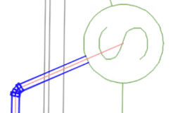
They’ve made it easier to deliver on bespoke design needs for major projects such as Civic Plaza in Surrey, BC. It’s the city’s tallest building and some of its guitar-pick-shaped skylight windows set the bar high for Starline’s capabilities.
“We could do circular shapes, but we had never attempted something so custom,” Walmsley says of the buildings nonstandard skylights. “They are huge—8 feet—so it was just an incredible feat to be able to put it all together and to coordinate. The lead time was extensive, and it was very challenging to get them to the building and installed on time.”
The Civic Plaza’s guitar-pick-shaped skylight windows put Starline’s capabilities to the test. Courtesy of Starline Windows.
Sustainable Benefits
Doing more with less but still doing it better is digital’s core mission. Walmsley says that for Starline, it’s made business planning easier and improved quality control. “Today, I can pull data from Revit, from Inventor, from our ERP and inventory-control systems to track all of the various activities happening and give upper management the information they need. It all adds up so that we know how many windows we can produce, how close we are to reaching project commitments, and when our next sale is due.”
Going digital has also had green benefits. It’s dramatically reduced the reliance on paper, as well as the volume of toner and other printer consumables the company uses. There’s also much less physical waste for disposal because more accurate design and manufacturing means fewer deficiencies and less cutting and trimming at the building site.
When deficiencies do occur, they can be captured and tracked to avoid replicating the same mistakes.
Walmsley says the real test, however, is how well a digital tool helps Starline work more closely with clients, partners, and other stakeholders: “It’s not just about us. It has to be beneficial to the architect, to the developer, and to the customer. In the end, the biggest selling feature is knowing we’re delivering something that’s going to make the building sell, that’s going to make everyone’s life easier, and that’s going to make people want to work with us again.”
As a structural engineer, I draw a lot of details and lay out a lot of plans. This means a lot of repetitive objects get drawn. How many times can you draw a 4×4 post or a beam hanger before enough is enough?
Thankfully, Bluebeam’s Tool Chest feature allows me to store and organize pre-drawn objects and groups into a tab for later use. If you have an object or group that you want to save for later, then right click it and select “Add to Tool Chest,” then select what folder to save it into. By default, there are some folders already for the general storage of saved objects. The “My Tools” folder is for creating custom hotkeys.
Folder management
To access the Tool Chest tab, click the Tool Chest tab icon, which looks like this:
Or press alt + x. At the top of the tab next to Tool Chest, click the downward caret symbol and select “Manage Tool Sets.” Within this new menu, you can add, delete, re-order, modify, import and export folders. If you’re just starting out, then you’re likely happy with just the default folders for now.
There are two ways to view the folders, which can be toggled by clicking the gear symbol to the right of the folder name within the Tool Chest tab and selecting either “Symbol” or “Detail.” Within the “Detail” option, you can rename the objects, which names can be seen when mousing over the symbols. You can modify the color and layer of objects within the folders by right clicking them and selecting the appropriate option.
Adding to the Tool Chest
Right click an object and select “Add to Tool Chest,” then select the subfolder. If you have a group of objects to save, first select all of the objects and then press ctrl + g or right click an object to be grouped and select “Group.” Then save it into the Tool Chest the same way as a single object. You can rearrange the order of the saved objects within the folder by dragging them around.
Using saved objects
You can bring a saved object into a document by clicking it within the folder and then clicking within the document. There are some advanced features such as sequencing, quantity legend and actions, among others, that are a topic for another time. If your “Reuse Markup Tools” feature from the F8 menu is enabled, it will continue putting in objects until you press escape or right click.
In this blogger’s opinion, this is one of the most complete mid-cycle updates in recent memory. Here are some highlights:
Performance
Always welcome!
Up to 60% Improvement During various operations including switching between drawings, corridor rebuild, and editing pipe networks.
Labels
Labels, especially when many exist in a Civil 3D drawing, can affect performance. All these settings are designed to boost performance.
Toggle labels on or off in Paper Space or Model Space If you don’t need to see labels right now, turn them off with a new setting.
Level of Detail on or off As you zoom out, labels will disappear.
Redraw options Choose when and how labels are redrawn.
Corridors
Users have been asking for this one for quite a while.
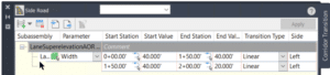
Transitions Use a tabular interface to define how subassemblies’ parameters transition between stations. For example, the daylight slope can be 2:1 at 0+000, transitioning to 4:1 at 0+050. Bus bays, or any lane widening can be defined this way. We are no longer limited to using polylines or alignments as width targets.
Profile Views
Display additional information about objects and their proximity to a parent alignment.
Point Proximity Band Show the distance between points and the alignment, and labels distances within the alert distance in red:
Alignment Proximity Band Show the distance between an alignment and the parent alignment and use ticks to show alignment segments within the alert distance:
Subassembly Composer
If you create your own subassemblies, these new features will benefit your productivity and help to reduce errors.
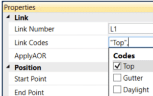
Point, Link, and Shape codes Define these codes in a dialog and apply them when and where needed.
Find and Replace Find and replace values almost anywhere in your code.
Dynamic Updates Change the source definition, and automatically update the instances.
Pressure Networks
Since Pipe runs, we continue to get useful features in this area.
Connect to Structures Pressure pipes can now be connect to pipe network structures and labeled.
Appurtenances Don’t Move These objects had the nasty habit of moving when the pipe run was edited. This is no longer the case.
Rail
These updates bring Civil 3D’s rail tool more in line with U.S. standards..
Turnout Blocks Turnout symbols can now be inserted perpendicular to the parent alignments.
Turnout Abbreviations Updated the abbreviation of critical points in the US turnout catalog in line with US regulations.
Project Explorer
Improve your reporting.
Property Set Objects Added support for reviewing property sets in the Project Explorer window.
Property Set Review
Added support for including property sets in object sets, reports, AutoCAD tables, and spreadsheets.
Property Set Values
You can determine the order and visibility of the value, description, and property names. Property set values can be edited.
Grading Optimization
Improve your preliminary grading.
Pathways Objects that represent sidewalks, driveways, and other ingress and egress paths.
Ridge Lines Objects that represent a linear elevation that directs drainage away from its placement.
Isolate Internal Zone Drainage You can now isolate drainage objects (drain lines, low points, and ridge lines) within a zone from affecting optimization outside of the zone boundaries.
Reducing 31200 hours of work annul= $1,872,000 CAD Saving
Remember when the architect sent over a change last week, what was the dimension we had to move that door by? You search through your notes and emails for several minutes before finding the conversation from last week that she’s referring to.
How much of an effect does this drag on productivity have on your day? In a 15-person office, each person can spend up to two hours a day searching for data-that’s $200,000 per year wasted!
Let us do a rough calculation here:
120 minutes X 300 employees =36,000 minutes
2400 minutes / 60 mins = 600 hours wasted each week
600 hours X 52 weeks = 31200 hours
31200 hours per year X $60 employment hourly rate =$1,872,000 CAD
$1,872,000 CAD/ a year of operation is wasted with unproductive work process.
SolidCAD has many successful cases in thriving BIM implementation in various cases. We have a great team of experts supporting individuals and organizations in terms of BIM training and helping them to set up a strong foundation project to reach independence.
1. Installation Package provides New PowerWeb IIS Application
2. Meridian E-Mail Manager Retired
3. The Default Store Table Data Provider is now Microsoft Access
4. Customizable PowerWeb JavaScript Modules
5. Meridian Cloud Rendering Profiles
MERIDIAN ENTERPRISE SERVER
What is Meridian Enterprise Server?
Meridian Enterprise Server is the core product in the Meridian Enterprise product suite. It provides centralized, scalable, web services and administration for use with Meridian Enterprise, Accruent Project Portal, and other business systems. Besides the shared services, Meridian Enterprise Server includes the latest generation of Publisher and Meridian Explorer technology.
MERIDIAN POWERWEB
What is PowerWeb?
Meridian PowerWeb is a web application designed to create, modify, documents and data stored in Meridian. Power users include Engineering Managers, Project Managers, Engineers, Drafting Technicians and Document Management. PowerWeb implements your company’s document and data lifecycle business rules, including automatic document naming, document filing, managing complex AutoCAD and other native reference files including exchanging AutoCAD data with Office files, and other applications.
PowerWeb is broken into several sub-sections
CONCEPT
FUNCTION
APPLICATION INTEGRATION
Application Integration: is provided by the Meridian Cloud Connector. The Meridian Cloud Connector can be downloaded and installed from the home page of the Meridian Cloud tenant. The Meridian Cloud Connector installs Site Cache with Local Workspace and provides application integration with MS Office, AutoCAD, and MicroStation applications.
DOCUMENTS
Documents: in a Meridian Enterprise vault are like files in a file system. They are in folders where you can copy, rename, move, and delete them. However, vault documents differ from files in a file system.
The fundamental difference between vault documents and ordinary files is that Meridian Enterprise distinguishes between a document and its contents. A document’s contents may be regarded as the file to which you are accustomed. Meridian Enterprise considers a document to be the file and its container (metadata properties). In Meridian, a document can exist without contents (for example, to represent a hard copy-only document), but contents cannot exist without a container.
EDM PRINCIPLES
Engineering data management (EDM): A generic term for a wide variety of functions. In general, it is the process of managing engineering documents throughout their life cycle, from inception through creation, review, storage, and distribution all the way to archiving or destruction. Depending on specific requirements, document management is different for every customer.
HISTORY
History: The Meridian history feature maintains all changes to vault data over time, including revisions to documents. History is enabled or cleared for each vault by a System Administrator.
The last released revision of a document is always the default one shown in a vault. However, by using the Show Revisions command, you can see all previous revisions and their effective dates
INDUSTRY-SPECIFIC
Industry Specific: Certain industries present unique challenges in document management. When configuring Meridian Enterprise for these industries, consideration must be given to document workflow, revision control, and project workflow.
NAVIGATION VIEWS
Navigation Views: Navigation views are different ways of viewing a vault for different purposes. Each view displays documents organized in a hierarchical tree structure like Windows Explorer, like the following figure. The tree structure is determined by a predefined set of properties. You can use Navigation views to find and select documents according to the property values of the documents. Navigation views help you to find documents based on whatever information you know about the documents that you want to find.
PROJECT WORKFLOW
Project Workflow: The project workflow is a simple two-step workflow that defines the current state of the project. There are only two states available in a project workflow: Open and Closed.
SCOPES
Scopes: Meridian manages a wide variety of documents and the information about them. Scopes are a way of limiting vault functionality and information to named sets that are easier to understand and use. You may select a scope that more closely meets your needs without experiencing information overload.
A scope is used to control the visibility of commands, views, and documents in PowerWeb. By default, PowerWeb provides the following built-in scopes that each correspond to a branch in the vault structure.
SEARCH
Search: It can find either documents or folders. It gives you complete flexibility of the search scope, properties, and conditions. Find can include referenced documents in its results and its results can be saved and shared with other users.
VAULTS
Vaults: A vault is a combination of a Meridian database and a document store. It contains all the documents you place in the vault, the data about those documents, all revisions of those documents made in the vault, and redline data for the documents. If some of your documents use references to other documents, such as with CAD files, then those references between documents will automatically be managed by Meridian. This means that you can move files between folders within the Meridian vault (such as from one project to another), and the references will not be lost, because they are managed by Meridian.
MERIDIAN EXPLORER
What is Explorer Classic?
Meridian Explorer provides an innovative way to browse and search for documents and tags stored in one or more vaults. The main benefits of Meridian Explorer are its powerful search, ease of use, extensive configurability, and scalability. You can easily navigate your way to the document you need and view its information with just a few mouse clicks.
Meridian Explorer provides you with text search capability on both custom metadata properties and document text content. You can also find documents by navigating a folder tree. Best of all, you can search a repository interactively by selecting from specific property values found in the current search results. With this method, you can quickly narrow your search from potentially hundreds of thousands of documents to just the documents you are interested in. Search results are presented in tabular format or as easily recognizable thumbnail images.
The Meridian Explorer Key Features Include:
Incremental synchronization of data, documents or assets and their related metadata from one or more Meridian Enterprise vaults to a Meridian Explorer consolidated repository.
Zero install, web browser-based read-only client. Management of change and engineering change requests.
Electronic redlines are available to be sent to vaults configured with the Meridian Asset Management Module.
Support for server-based viewing.
Configurable property pages, search pages, and views.
What is Cloud Explorer?
Cloud Explorer is a web application for searching and retrieving engineering information.
Target users include Maintenance Managers, Planners, Engineers, Operations Managers, and Operators.
Cloud Explorer allows you to easily locate data, documents or assets and see their related references within your browser. By default, when the Explorer is opened the Explorer Landing Page allows you to view all the data, documents, or assets in the repository, depending on which view is active, Documents or Assets.
If Explorer was opened by another application such a computerized maintenance management system (CMMS), you might be viewing only the items in the repository that are related to a document or asset in the other application.
Only documents in the Master or Documentation scopes of a repository are available in Explorer. Data, Documents or Assets in a project or that are archived are not available to you. Filters are implemented to view the items that meet your required criteria.
CONCEPT
FUNCTION
ASSETS
Assets: By default, when Explorer is opened from the landing page, you can see all the assets in the repository, depending on which view is active, Assets. If Explorer was opened by another application such a computerized maintenance management system (CMMS), you might be viewing only the items in the repository that are related to an asset in the other application.
DOCUMENTS
Documents: Cloud Explorer lets you easily find documents and see their related counterparts right in your browser. By default, when you first open Explorer from the landing page, you can see all the documents in the repository, depending on which view is active, Documents. If Explorer was opened by another application such a computerized maintenance management system (CMMS), you might be viewing only the items in the repository that are related to a document in the other application. Only documents in the Masters or Documentation scopes of a repository are available to you in Explorer. Documents in a project or that are archived are not available to you. You can use filters to see only the items that meet criteria that you determine.
INTERGRATION URLS
Create Integration URLs: You can create dynamic URLs that link users to their asset documents in Explorer. This functionality is typically used with our integrations with CMMS- or GIS-type applications like Maintenance Connection, Maximo, or SAP.
SAVED SEARCHES
Saved Searches: Saving a search stores your search filters so that you can return to the same list of items later. Saved searches, you can:
§ Overwrite an existing saved search with a new result set,
§ Revise the filters and save the new criteria,
§ Share a saved search with another person,
§ Delete a saved search you no longer need
SIGN-IN
Meridian Cloud Sign: Allows you to sign in with either your Google, Microsoft Windows Live, or Azure AD account. You must have an account with one of these services to use Meridian Cloud. Additionally, if your System Administrator has enabled SAML, you can sign in using a SAML Identity Provider. The email address that you use to sign in can be different than the one which was used to invite you.
MERIDIAN PORTAL
What is Meridian Portal?
Meridian Portal is a web application designed to allow Project Documents, Data and Asset Collaboration. Users include Document Management, External Contractors, Regulatory Organizations, and other External End Users.
Meridian Portal provides a Personal Dashboard with Project Document, Data and Asset status reports and packages workflow progress. Meridian Portal contains a central repository for Project Documents, Data and Asset with text search and dynamic filtering to allow users to quickly find what they require. Specific document detail views can be implemented for internal and external use.
The Meridian Portal Key Features of Include:
Internal and external collaboration in a secure cloud-based project portal
Easy-to-use task-based user interface
Formal and informal work packages information exchange
Collaborative document review and approval processes
Automated document compliance and completeness checks
Full audit and history log on actions performed by internal and external participants
CONCEPT
FUNCTION
AUDIT TRAIL
Audit Trail: Meridian Cloud keeps track of almost every activity in the system. Administrators can trace user authentication, access logs, project activities, and even electronic signatures, which are critical for the life sciences industry.
CLIPBOARD
Set Under Change: When a package is received and accepted from a contractor, small modifications on the received documents may be necessary. To support this the documents can be assigned to an internal member.
DASHBOARDS
The Dashboards: Give you valuable insights to your projects, packages, and documents in one place. With them, you can view a variety of metrics and filter the results by project names and dates. If desired, you can export the data in spreadsheet formats for further analysis.
DOCUMENTS
Documents in Portal: Documents are combinations of files managed by Meridian users via one or more workflows. Documents are composed of three “parts”: The source file, the rendition (which can be generated in the system), and the document metadata. Document metadata consists of document properties, used to capture information to describe the document details. As documents are revised, Portal tracks the changes to the document and records these changes as are saved as revisions in the document’s history.
PACKAGES
Packages: Meridian Cloud packages contain documents for the exclusive use of the project members to which the packages are issued. Packages can be used as submittals and transmittals between project teams. A transmittal sheet (Microsoft Excel workbook) is included for package content verification. Packages are also used to exchange documents between Meridian Cloud and Meridian Enterprise. Project members can download documents from packages. Meridian Cloud assigns a status to each package for each step in its life cycle to make finding, tracking, and processing packages easier.
PROJECTS
Projects: The primary workspaces in Meridian Portal. After you create projects, you can invite others to join the projects via email. Meridian Portal uses containers called packages within projects to assign sets of documents to other project members for action. After the recipients accept their project invitations, they can work with the packages that are assigned to them. They can also upload documents of their own to packages in the projects.
Projects in Meridian Portal can be linked to projects in PowerWeb at the project-level.
QUICK SHARES
Quick Shares: Quick Share is a temporary package that you can create to share documents with other project members securely. Quick Shares expire after 30 days and then are deleted automatically. They are not otherwise tracked by Meridian Portal, so you should use them only for informally sharing documents, not as official transmittals.
To learn more about how Meridian 2022 and the CMMS solution can help your team, don’t hesitate to contact the SolidCAD Meridian Team.
Recreating a Civil 3D template from scratch is not something we look forward to, but it may be necessary at times. Read on to find out more.
You may ask why one would need to do this. Some users will do this when they upgrade to a new Civil 3D release. I have not seen any evidence that would convince me to do this. The only time I would recreate a template is if there is a serious problem that can’t be fixed without it. The recover command does a very good job at removing anomalies that may arise between Civil 3D releases.
So, you’ve decided to do it. What to do? There may be further steps that what you see below, but these will go a long way to making this arduous task a little more pleasant. The workflow below assumes that your original template is not completely pooched and can be successfully inserted into your new file.
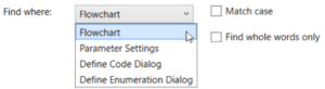
1. Open problem template:
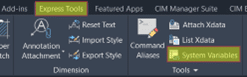
Export system variables to a file.
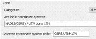
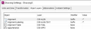
Note the assigned coordinate system in Civil 3D Settings, Files tab.
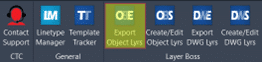
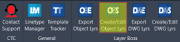
Use this CTC tool to export the Civil 3D Object Layers to a file. It is found in the CIM Manager Suite.
Civil 3D’s Import Styles and Settings tool does a poor job of restoring these. If you don’t own CTC tools, enter Civil 3D Settings and note all the object layer settings so they can be restored in the new file.
Export any Layer Filters. If you’re using Civil 3D, this is easy.
Export any Layer States.
Export any Property Sets (if you are using Civil 3D).
2. Begin a new blank drawing using the acad,dwt or dwt files, and save the drawing.
3. Import system variables from the file you saved earlier. There are many settings saved in a DWG that must be restored.
4. Import the Layer Filters.
5. Import the Layer States.
6. Import the Property Sets and check any label styles where they are referenced to ensure they operate properly.
7. Insert problem file and explode. Purge anomalous blocks if necessary.
This step will insert most of the styles and any pre-configured objects like Point Grous, Surfaces, Pipe and Pressure Networks.
If the original file is too far gone, skip this step. You will need to recreate any pre-configured Prospector objects.
8. Set the coordinate system if there was one set in the original template.
9. Import styles and settings from problem file.
If you skipped step 4, note that this command DOES NOT import everything. See this document for more information. These may need to be dragged and dropped form the original or recreated.
10. In the Prospector, inspect the names of any pre-configured objects and adjust if necessary.
11. Use this CTC tool to import object layers from the file you exported previously.
Restore them manually if you do not own CTC Tools.
12. Import paper space layouts from problem file.
13. Close the new file and run the RECOVER file to open it and check for problems.
14. Recreate the Scale List.
This can be easily done by creating some text in the original file and assigning all the scales to it. Copy this text and paste it into the new file then delete the text. New scales will now be available.
15. Test, test, test. To make sure everything works as it should.
16. Of course, make a backup of the original file and SAVE the new file with the original name.
Disconnected Workflows: separate tolls being used by project stakeholders and disconnected workflows internally with firms result in the costly duplication of effort and increase work time.
The inability to engage in influence early: This adds risk to securing procurement paths and is made even more difficult with those disconnected workflows and disparate solutions.
Fast-tracked project schedule: Meeting tight deadlines are tough enough with managing and coordinating materials and labour, but it is even more difficult if there is miscommunication and design intent.
A small talent pool: Difficult to hire and retain talent. It is also a problem that older specialists are retiring from the industry and taking their experience with them
SolidCAD has many successful cases in thriving BIM implementation in various cases. We have a great team of experts supporting individuals and organizations in terms of BIM training and helping them to set up a strong foundation project to reach independence.
Feel free to contact us for more information.
#SolidCAD #Digital Collaboration # Increasing BIM Mandates, #Technology Proliferation #Industrialization of Construction #Digital Transformation