
TORONTO, ON – June 27, 2023 – SolidCAD, a prominent Autodesk Platinum partner and professional services firm based in Canada, is delighted to announce its expansion of the Chaos product line with Enscape, which provides industry-leading real-time visualization workflows for architects. In 2022, Enscape merged with Chaos, forming a powerhouse in 3D visualization and design workflow technology. Together, the combined entity focuses on developing cutting-edge 3D visualization solutions for clients in diverse industries such as architecture, engineering, construction, product design, manufacturing, and media and entertainment.
By joining forces, Chaos and Enscape are committed to bolstering their product lineup, aiming to offer customers a comprehensive end-to-end visualization solution worldwide. SolidCAD is thrilled to incorporate another visualization tool into their offerings, alongside Chaos’ existing portfolio of V-Ray products and Corona. This expansion will greatly benefit SolidCAD’s customers in North America, empowering them to elevate and reimagine the way they bring their designs to life, from concept to construction.
“SolidCAD has always put the goals and needs of our customers first,” Marcus Tateishi, President at SolidCAD states. “We want to help our clients overcome visualization challenges and deliver exceptional outcomes. By adding Enscape to our portfolio, we can help our clients translate their design concepts into captivating visualizations, and drive success in the AECO space. We are particularly excited to announce that we will be able to support customers across North America, in primarily Canada and the U.S. This will be an advantage to firms with offices in both countries, enabling quality professional services and customer success experiences.”
“SolidCAD has been an exceptional Chaos partner for over a decade, helping us bring the best 3D visualization software to North America” Kalin Vasilev, Channel Manager for Chaos states. “With the merger of Enscape and Chaos, we are excited to collaborate with SolidCAD on this new chapter of our partnership. Together, we are committed to offering the most comprehensive end-to-end 3D visualization ecosystem to design professionals in Canada and the United States.”
Join SolidCAD for an overview webinar on July 25 at 10:30 am PT/1:30 pm ET to learn more about the capabilities of Enscape. Register here.
About Enscape
Enscape is a high-quality real-time rendering, visualization, and virtual reality software that integrates design and visualization workflows into one. Enscape gives designers the power to create realistic renderings based on their existing planning data and easily produce videos, panoramic images, and VR simulations. Enscape software is compatible with Revit, SketchUp, Rhino, Archicad, and Vectorworks and is used by renowned architecture firms in over 150 countries.
About Chaos
In 2022 Enscape merged with Chaos to create a global leader in 3D visualization and design workflow technology.
The newly-combined company, which retains the name Chaos, develops 3D visualization technology for architecture, engineering, construction, product design, manufacturing, and media and entertainment. Creating intuitive and powerful workflows for participants across the entire design spectrum, Chaos aims to develop and strengthen its product portfolio to create a comprehensive end-to-end visualization ecosystem designed to meet the evolving needs of its customers.
The company’s product portfolio includes V-Ray, a physically based renderer honored with an Academy Award and an Engineering Emmy; Enscape, a high-quality real-time rendering, and virtual reality plugin; Corona, a high-performance photorealistic rendering engine; and Cylindo, a 3D furniture product visualization platform for commerce.
Headquartered in Karlsruhe, Germany, Chaos is the largest global 3D visualization company with more than 700 employees and offices worldwide.


 Benefits of Accruent Meridian


 ACC
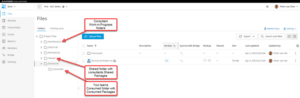
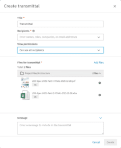
ACC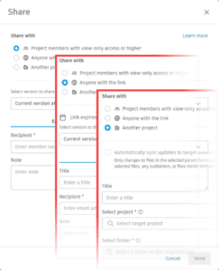 Sharing with Project Members allows you to share files with other project members who already have at least view-only permissions for the file. Simply navigate to the Files section in Docs, select the desired files, and click on the three dots at the top. Choose “Share” to access the sharing options. From there, you can send files to project members via email directly from
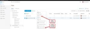


_hr")
")


")