• BIM 360 Design – the next gen of Collaboration for Revit

    As of April 9, 2018, Collaboration for Revit is available as BIM 360 Design – Autodesk’s next-generation cloud work-sharing, data management, and design collaboration product.

    This is part of several changes to the Autodesk BIM 360 portfolio of products.

    Collaboration for Revit (C4R) background

    Collaboration for Revit (better known as C4R) was one of the most successful products from Autodesk. It was a simple product, but it provided a service not available affordably through any other means.

    Collaboration for Revit gave users on project teams, not in the same office, the ability to work together in one model. Prior to its release, Revit worked well within an office; not so well between offices. With the arrival of C4R, in one fell swoop, those barriers were eliminated.

    What has changed?

    BIM 360 Design is the next generation of Collaboration for Revit (C4R). It enables the cloud worksharing you’ve come to love in C4R but connected to the next generation BIM 360 platform.

    With the new changes, everyone will have more seamless access, whether in BIM 360 Docs or Design (C4R) as they will both sit on the new Autodesk BIM 360 platform.

    You will have access to the Design Collaboration and Document Management modules in BIM 360, in addition to the existing C4R functionality.

    The following list describes the modules included in each product:

    BIM 360 Docs

    • Document Management
    • Insight
    • Project Adminstration
    • Account Adminstration

    BIM 360 Design

    • Document Management
    • Design Collaboration
    • Insight
    • Project Adminstration
    • Account Adminstration
    • Access to Revit Cloud Worksharing
    • Access to Classic C$R
    • Access to BIM 360 Team

    What does it mean for you?

    • Current Collaboration for Revit subscribers:
      • Can activate access to BIM 360 Design via a link in their Autodesk Account; and,
      • Will be eligible to renew to BIM 360 Design with access to BIM 360 Team.
    • Current BIM 360 Team subscribers will be offered access to the new BIM 360 platform via Autodesk Account.

    What about compatibility between the two environments?

    Because BIM 360 Design (C4R) will be running on the new BIM 360 Docs, files stored in the old – “Classic” version of C4R will not be compatible with those on the “New Generation” version. Therefore, it is crucial that one has the proper number of Classic licenses before upgrading.

    In addition, if you will be sharing a project with other firms, it is also important that they have adequate licensing.

    Q & A for the Next Generation BIM 360 Platform

    The following are some key questions based on Autodesk’s FAQ for the BIM 360 platform.

    1. Can classic services and next-generation BIM 360 modules be utilized on the same project within a customer account?

    No. BIM 360 Glue and BIM 360 Build subscribers must select whether to activate next-generation BIM 360 modules, or to activate classic services, when setting up a new project. BIM 360 Team projects and data will remain separate from the BIM 360 platform. Projects and data created in one will not be visible in the other.

    2. How will renewals be handled for Collaboration for Revit?

    Collaboration for Revit subscribers will be eligible to renew to BIM 360 Design.

    Collaboration for Revit customers that maintain active subscriptions to BIM 360 Design will retain access to their projects and data in BIM 360 Team and will also have access to the BIM 360 platform with new and improved features and workflows including greater file- and folder- based access controls, unlimited storage, facilitated model exchange, and change visualization.

    3. How will renewals be handled for BIM 360 Team?

    Existing BIM 360 Team subscribers will be eligible to renew their BIM 360 Team subscriptions at the same price. Customers that maintain active subscriptions to BIM 360 Team will retain access to BIM 360 Team projects and data and will also be provided access to the new BIM 360 Platform.

    If BIM 360 Team or Collaboration for Revit customers decide to NOT renew, upon the end of a subscription, all project files can be downloaded. Project data will be maintained in customer accounts after the end of the subscription for a period of time as specified in the Autodesk Trust Center.

    4. Will current C4R subscribers be able to continue to use the product as they do today?

    If you are an existing Collaboration for Revit subscriber and you maintain an active subscription of Collaboration for Revit, you can store, access, and manage project data and perform cloud worksharing in either BIM 360 Team or the new BIM 360 Platform.

    5. Which Revit versions will work with Collaboration for Revit and BIM 360 Design?

    • With Revit 2015 to 2018.2 and earlier versions, you can cloud workshare in Collaboration for Revit.
    • With Revit 2018.3, you can cloud workshare in both Collaboration for Revit as well as BIM 360 Design.
    • With Revit 2019, cloud worksharing will be exclusive to BIM 360 Design.

    6. Where can I find more technical information?

    The Autodesk Knowledge Network has published this guide to BIM 360 DesignContact our Support Desk if you need more information.

    Auto-numbering parking stalls using Dynamo

    This article describes how to use Dynamo to number parking stalls. Numbering parking tags can be tedious doing manually. If you have to number or renumber parking stalls and you are looking for tools to do it in an efficient and quick way, this can be a great opportunity to use Dynamo and automate all this work. The process demonstrated in this post was tested in Revit 2017, Revit 2018, and Revit 2019 using Dynamo 2.0.

    1. Place the parking stalls and load the parking tags into your project.
    2. Select Tag All under Annotate tab then select the Parking Tag family and click okay.
    3. Download the dynamo script and save on your computer. Open the Dynamo player and select Browse to Folder to navigate to a directory containing Dynamo scripts and click OK.
    4. Select Run Script on the right side of the dynamo script you are going to use.
    5. Another window will pop up asking for the inputs. Draw the spline over the parking stalls and click Select under Select Model Element in Dynamo Player. Then click at the spline
    6. Under Number, write the number that will represent the start number.
    7. Press Run Script again to activate the command.

    Download the Dynamo script for auto-numbering parking stalls.

    Revit 2019: Essentials for MEP Engineers

    Getting started with Revit can feel daunting. It’s an unfamiliar program that may not work like your current software. But, like anything new as you become more familiar with it you will start to see the benefits of the basic modifying tools – Copy, Move, Align, Offset, Mirror, Array – as well as the special tools it offers like Systems, Analyze, and Collaborate all within a 3D environment. Layers, often an irritation, don’t even need to be thought about in Revit. Revit will place every object in the correct layer. You do not need to switch Ortho on/off or change Snaps. Revit will show alignment lines, angles, snap points on the go.If you are just starting out in Revit, here is some basics that you should know:

    Model
    Revit creates a virtual 3D representation of the model with the established relationships between elements.You can create as many views as required by the project. Every view of the model is a live view of the parametric elements. If an element is moved in one view, the position of that element in all of the views is instantly updated. Therefore, changing the elements will change the model instantly and all changes will be reflected on each view and plot sheets.

    Model elements
    All of the elements in Revit are Families and represent real objects. Families are grouped and sorted by category in the content libraries and in the Project Browser. The families, such as air terminals, plumbing fixtures, and mechanical equipment, are loaded into the template of the project or into the model from the Revit library or an external source. For example, from the manufacturer’s website or Autodesk Seek. All Families in Revit are parametric.

    Instance and Type properties
    Model elements in Revit represent physical instances in a model. When placed in a model they are visible in all views.

    Type properties for the family are common for all types of the same family and contain information that applies to all instances of the same family type in the model. For example, type properties for an air terminal will be size – length x width. Changes made to type properties affect all instances of the family created from that type. Revit allows to change the family with a different type using the Type Selector. It is easy to create a new type within the family using the Duplicate function in the Type Properties dialog.

    Instance properties contain information related to a specific placed instance of the family element in the model. For example, instance properties for an Air Terminal will be Air Flow. Changes made to instance properties affect only that instance of the family.

    Annotation elements are also families that are used to add dimensions, notes, and tags to a view.

    The first Revit project can be a frustrating one. You will be learning the program while you are working on your project. Even if you had some training, you’ll quickly find that not everything will work like it did in your training sessions in a real project. All the elements are drawn to real size and you need to be attentive to clashes while working on your model.

    There are some little things you’ll want to remember:

    • Remember to place Air terminals or Electrical fixtures at the right elevation. Default for Air terminals is 0.000 and needs to be changed to match ceiling height. You also need to assign Flow to Air terminals.
    • As soon as you start a layout of the ductwork, Flow will be calculated through the system. You do not need to insert fittings working on ductwork or piping layout, Revit will do that for you.
    • Keep the section or 3D view of the area you are working on open. Don’t create sections just because you can; create one vertical and one horizontal, move them around as needed; create a new one when necessary and delete it once you are done.
    • When you have placed MEP elements into a model, you can generate a duct or pipe layout manually, or Revit can generate it automatically from different layout solutions.
    • A parameter that defines the system is the Connector that is located within model elements and has pre-defined classifications within Revit. If you cross two ducts or two pipes with the same system classification on the same elevation, Revit will join those systems by creating a fitting. If this is not what you intended, place the systems on different elevations.
    • One Model element can have a number of different connectors with pre-set system classification, so elements can be assigned to a number of systems. A set of logically connected elements creates a system.
    • All components and systems can be seen in the System Browser – a tool that displays a hierarchical list of all system components in each discipline in the model.
    • Annotations are view-specific; they appear only in the view in which they were placed. Annotations can be copied from view to view, but any changes made to them in one view will not be transferred to any other views.

    Now open Revit, select the System tool, drop some Air Terminals, place some ducts and now you can see the system you created in 3D. Wow! It looks impressive. But more impressive is the fact that you have not only created a system, and sized the ductwork with one click, you have also produced a section and a schedule which will be updated as you are working on the model. Revit has the ability to perform calculations such as pressure loss and static pressure, size ducts and pipes, and perform energy analysis on the design.

    Contact us to find out more about Revit for MEP and how we can help you get the most from it.


    Revit Family Guide – Master Revit Families in 10 Steps

    A Family is a group of objects that form a building component such as a door, a wall, a window or a chair. All families are associated to a specific category and contain a set of properties (parameters) and a graphical representation associated to these properties.

    Understanding how to create and edit Revit Families is a must if you want to take your Revit skills to another level. Revit’s Family Editor has all the tools you need to create custom components for your Revit projects, and here you will learn 10 steps to master this environment.

    #1 – Understand family types

    There are different Family Types in Revit:

    System families – Generally, assemblies (walls, roofs, floors, ceilings, etc). Our flexibility here is limited, we can create different types of system families, but we can’t add parameters to control their graphical representation.

    Component families – Families we can create from scratch and load into the project. Can be extremely flexible and customized based on your needs. In this blog post, we are going to focus on them. They can be hosted, free standing or work plane-based.

    In place families – ‘One-off’ families created inside the project environment that do not require geometrical flexibilization. Should be used with caution, as they can increase the size of the file and impact model performance.

    #2 – Understand the use of parameters

    Parameters are used to define and modify elements in Revit. They give flexibility to project components. By changing the parameters assigned to a family we can create different versions of the family, called types. Each family type has an identical set of parameters called “type parameters”.

    When placing a family type in a project, you create an instance of that element. Each instance has a unique set of parameters called “instance parameters”. By changing these parameters, you can apply changes independent of the family type, that will only apply to that specific element in the project. Keep in mind that if you make any changes to the family type parameters, the changes apply to all element instances that you created based on that type.

    It is up to the person creating the family to define its parameters, and to determine if a parameter is going to be applied to the type or to the instance level. The following pictures are a good example of that statement. These two doors are very similar graphically, but each one has different instance and type parameters – for example, one door has a parameter called “Door Material” and the other “Panel Material” with, essentially, the same function. Why? Probably just because they were created by two different Revit users.

    #3 – Plan before you start

    Planning is a key process to successfully create a family in Revit. Sketch you family in a piece of paper, to make sure you don’t get carried away in the process. It is common for new Revit users to feel that they should “model everything” in full 3d, but following this road usually leads to over modelled elements that are hard to use and manage.

    Answer the following questions before you go to the next step:

    #1 Is there a family in Autodesk’s library that is similar to the one you want to create? Consider copying, renaming and modifying the existing family to save time.

    #2 Where will the family be viewed? Is it only showing in plan? Is a 3D representation required? Will it be rendered? Can we get away with 2D lines? Only model in 3D what is necessary.

    #3 How do you want it to graphically show in different views? What is the level of detail you need based on the scales of the drawings in which it will be represented? Consider setting visibility controls.

    #4 What is the level of flexibility you need? What properties do you want to be able to control? What parameters must be created? Is a property dependent on another? Consider creating formulas to create relationships between parameters.

    #5 Will the family be scheduled? Is a parameter going to be scheduled? Consider using shared parameters.

    #4 – Select an appropriate template

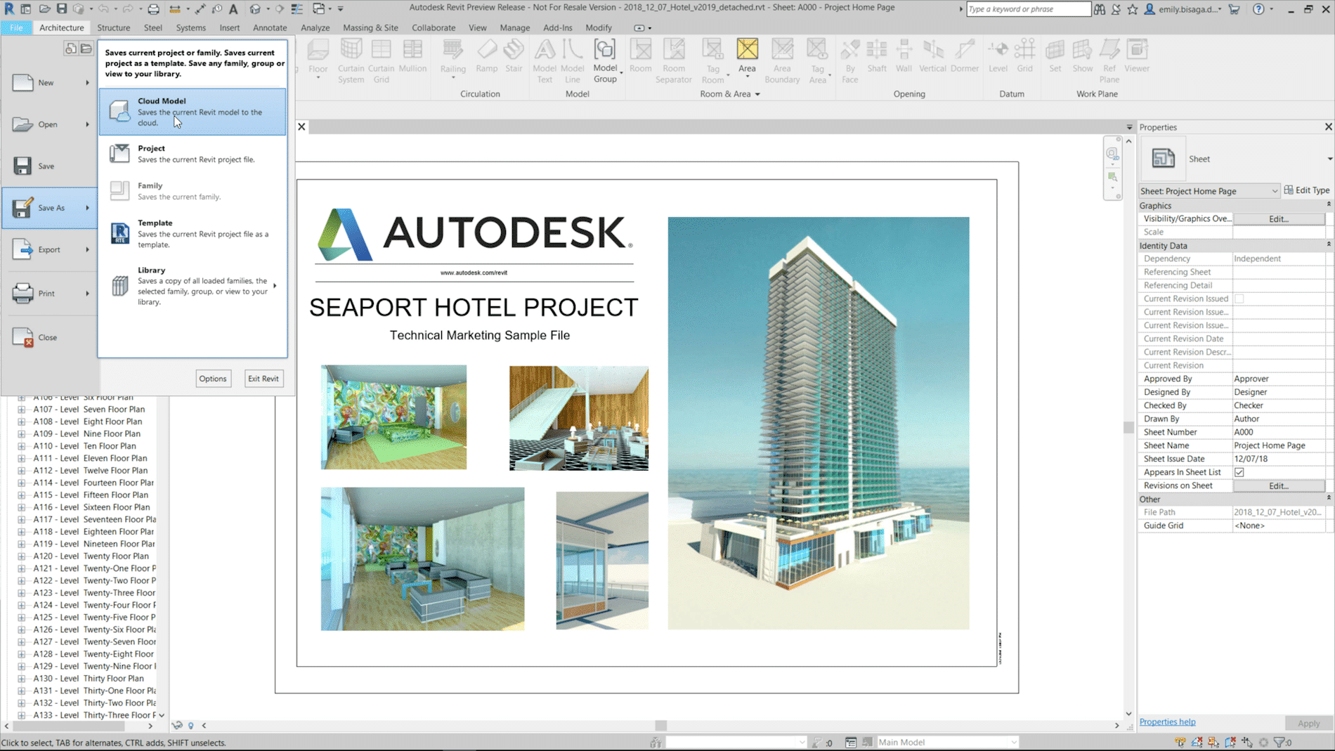
    Revit comes with a variety of templates based on object categories. Go to File > New > Family and select an appropriate Template for your family. Categories will determine the behaviour of the family – for example if the family goes from level to level, or if it is hosted in another element. If you are not sure what category the object falls under, then create it as a generic family and you can modify the category later going to Create > Properties Panel > Family Categories and Parameters. Be aware that object categories are what control the display of objects in Revit and several categories are “non-cuttable” in Revit.

    #5 – Create the family framework

    Most templates come with, at least, two pre-defined planes. The intersection of these two planes defines the origin of the family. If you want your family to be able to change in size, you need to build a framework using reference planes and/or reference lines (used to constrain angles).

    Use reference planes to set critical positions in the family. Later, we will constraint the geometry of the family to these reference planes so when they move, the geometry follows.

    The picture below shows the reference planes you would create if you wanted to create a table – reference planes in plan view for the table top, and reference planes in an elevation to set the top and underside of the table top.

    #6 – Dimension the framework

    Go to Modify > Measure Panel, select a dimension tool and dimension your framework. Then, create constraints defining both flexible and static conditions.

    Select and lock a dimension.

    Select and set a group of dimensions as equal with the “EQ” option.

    Label a dimension with a parameter to be able to control its value dynamically. Select a dimension, go to Label Dimension Panel and click Create Parameter. Give the parameter a name, a group and define if the parameter will be applied to type or instance (you can change this later). Notice that if you select a dimension, the dialogue defaults the parameter type to dimension, and length.

    In our example, the table top length, width and thickness are flexible and labeled with parameters. Equality constraints have also been included so when Length and Width change, the center remains in the same position. The Height of the table, on the other hand, is fix and locked as 970 mm. No parameter was created, because there was no need to make it flexible.

    After setting your parameters, you can edit them inside Modify > Properties panel > Family Types.

    The blue heading bars in the picture above are the groups under which you can create each parameter. Make sure you group your parameters in a logical and ordered manner (you can move parameters up or down and edit their groups if you need).

    The name of a parameter is also very important. Use short but descriptive names and don’t use ‘-‘ signs because Revit may confuse them as formula values. Also keep consistency for naming conventions – will they have first letter cap, all caps or all lower case?

    Notice that parameters can also be driven by formulas. In the example below, the Width was set to be half the Length. It is also possible to insert conditional statements. Conditional statements can contain numeric values, numeric parameter names, and Yes/No parameters.

    Before going to the next step, test your parameters and see if the reference planes are moving the way you expected. Insert new values and hit Apply. Use values outside the anticipated range. If your framework has a glitch, now is the time to fix it.

    #7 – Model and constrain the geometry

    After creating the framework and the constraints, and making sure they are going according to plan, it is time to add the geometry. Go to Create > Forms Panel and select an appropriate massing tool – Extrusion, Blend, Revolve, Sweep, Void.

    Draw the geometry and constrain its edges to the reference planes using the align tool. Finish the sketch and align/lock the geometry in other views if applicable.

    Once you have locked the geometry to all applicable reference planes, it’s time to run additional tests to see if the family is working properly.

    Avoid creating addition dimensions and reference planes inside the Sketch Mode. They will not be visible once you leave the sketch and will make it hard for you to manage the family in the future. Additionally, avoid constraining modelled elements together – always prefer to constrain modelled elements with reference planes instead. This will reduce the risk of having family crashes and corruption down the road.

    Repeat the process to include all the geometry you need in the family – create a framework, constrain the framework, add geometry, constrain geometry to the framework, test it. Keep in mind that creating a family in a slow-paced manner, running constant tests, is the best way to succeed. If something goes wrong in your parametrization, you might have a hard time to find and fix the problem if you implemented several untested changes all at once.

    #8 – Improve your family

    Improve your family by creating additional geometry, parameters and relationships.

    Add shared parameters for information you need to schedule or tag in your project.

    Set materials to your geometry. If the material of an element will always be the same, select the element, go to Material field and hit the “…” to select a material. If the element may have different finishes, create and apply a parameter by clicking on the box on the right side of the Material field (marked in yellow in the picture below).

    Set visibility yes/no parameters to elements if you want to be able to control if they are visible or not. To do that, select the element and define a parameter by clicking on the box on the right side of the Visible

    Use nested families to make changes more efficient and shift from one family type to another using a “Family Type” parameter – see how leg types are controlled in the example below.

    #9 – Add visibility controls

    By selecting each element and setting a Visibility Setting, you are able to control the level of detail and the view types in which your elements will be visible. This can be useful, for example, if you want to use simplified 2D lines to represent a family in plan and elevation but wants to see all modelled components of that family in a 3D view.

    For greater control and flexibility, Revit allows you to create subcategories of the any category in the family editor. Go to Manage > Object Styles and create a new subcategory. Then, select the element and apply it using the Properties Window.

    #10 – Create Family Types

    Before you load your family into a project, go to Modify > Properties Panel > Family Types and create default types. Use descriptive names that reflect the type parameters that are part of the family.

    Now it is your turn

    In this blog post we covered the main concepts and tools for you to create powerful and flexible families for your Revit projects. Now it is up to you to create your first family. Start with a simple family and go through all the steps listed above.

    Creating Revit families can be intimidating at first but, once you understand the concepts and get used to the process, you will be able to explore endless design possibilities without depending on 3rd parties’ content.

    New in Revit 2019 – MEP Engineers improvements to primary/secondary hydraulic

    Revit 2019 has arrived, and with it comes a number of great new features and enhancements for different uses.

    • BIM 360 Design is the re-branded C4R
    • Open Dialog Enhancement to show version of the Revit file
    • Publish Settings Dialog changed
    • Multi-Screen Support & Tabbed Views
    • Graphic Filters – added “or” variable in the view filters
    • Levels in 3D
    • Uncropped perspective views
    • Double fill for complex graphical rendering
    • Split Railing
    • New Steel Design Tools
    • Dimensions for Curved Objects
    • Vertical Text Alignment in annotation tab
    • Hydraulic system loops separation
    • Parallel Pumps Sets (Duty/Standby)
    • Analytical connection

    The main improvement for mechanical engineering is in flow and pressure drop calculations for hydronic piping networks in hydraulic system loops and Parallel Pumps Sets (Duty/Standby). With this new version of Revit, complex networks can be separated into primary/ secondary loops using the Hydraulic Separation feature. In this post we will take a look at how this hydraulic system separation feature works, how to enable visibility and how to set up parallel pump sets for these calculations.

    Hydraulic Separation for Hydronic Piping Systems (Primary/Secondary)

    Hydraulic Separation is a continuation of the improvements added for closed-loop hydronic networks. The pressure drop is calculated independently for each loop. The “Add Separation” Button and the Loop Boundary parameter has been added to pipes assigned to hydronic systems. This is the read-only parameter and was added to the pipe parameters to indicate whether it is a boundary for the loop.

    In the process of design, you need to configure primary/ secondary loops and understand where to input data when defining the piping system. This is an important step because without it, separation of primary and secondary loops will not work. However, when designed properly, Revit can calculate flow and pressure drops in the network.

    In order to take advantage of this new separation feature, you need to configure your system as a real working system. Also, you must check the “Enable analysis for a closed loop hydronic piping network” property in the Mechanical Setting dialogue to enable this feature. By default, Revit will calculate the pressure drop using the Colebrook Equation. However, the Haaland Equation is also an option if selected in the drop-down menu in the Pressure Drop tab.

    How does this feature work?
    It separates primary and secondary loops of the piping system to calculate the flow and pressure loss for each loop.

    How to design it:
    You need to create a hydraulic system, a direct return or a reverse return loop system. A closed loop hydronic piping network must contain:
    Hydronic piping networks are defined as having:
    • A single source equipment component, such as a boiler or chiller. This component is optional.
    • A single pump or pump set per loop (primary, secondary, tertiary, and further) if you want to calculate flow and pressure drop for each loop.
    • Any number of loads, such as radiators or fan coil units on the secondary and/or additional loops. Radiators and other terminals can be piped in series.
    • Any number of pipe segments in the supply sections and return sections of the network.
    • The primary loop configured in a loop or using a header.

    You will see the loop boundary separation in your drawing shown as a ‘V’ mark at the connection. Pay close attention to these markings as they can appear very small in drawings.

    Make sure Hydronic separation symbol is turned on in Visibility Graphic dialog box.

    Parallel Pumps Sets (Duty/Standby)

    Autodesk added capability for Mechanical Models to utilize pumps operating in parallel conditions to strengthen flow and pressure loss calculations.
    The setting up parallel pump set determines the number of pumps that are running on Duty/Standby mode at a time. This information is used by the flow and pressure calculations for proper sizing of the branches and header of the pump set.

    We can specify or change the number of pumps on duty and on standby in the Edit Piping System tab for each pump set.

    Select Pump > Go to Edit Piping System tab > Add Pump to Set button > Select Pumps you wish to add to set > Specify numbers of pumps on duty and on Standby > Finish editing system.

    This information is used by the flow and pressure calculations for proper sizing of the branches and header of the pump set.

    Analytical connection

    The analytical connection uses a point on the perpendicular projection from the connector on the family. If a perpendicular point doesn’t exist, the connection is added to the closest end of the pipe.
    If the selected pipe has an open-end connector, the analytical connection will attach to the open pipe connector. You can turn off the display of analytical connectors, and the flow and pressure properties from the equipment will continue to be used with the network calculations. On the View Control Bar, click “Hide Analytical Model”.

    You can assign a pressure drop in the Type Properties dialog for Analytical Pipe Connections. The property defaults to zero.

    Conclusion:

    With new great features of Revit 2019 you can now design separation loops, which greatly helps with calculations and increases productivity. This includes primary and secondary separation loops, pressure drop and flow calculations for each loop, and setting up parallel pump sets. There are also new Calculation settings in the Mechanical Settings Dialogue that defines the calculation formula and enables the analysis.

    Implementation and BIM

    What is this thing we have been calling BIM “implementation” for so many years? As a professional who has been working in and around the move to Building Information Modeling for over 15 years, I am appalled at how few people I have seen that would really consider themselves successful with the change to it.

    Why is this? I would suggest that it is because of this elusive word – implementation. Everybody talks about it, but what they really want is a quick fix to a very complex challenge – a little bit of training here, creation of a little bit of content there, a pretty rendering, some “clash-detection”, some “how to’s” – the challenge of taking a bunch of disparate participants and bringing them all together into one cohesive environment.

    So, let’s have a quick look at the meaning of the word implementation and see how it applies to the move to BIM and a true digitally deliverable that provides value to all participants.

    “The process of putting a decision or plan into place”

    Process: Everyone seems to talk of how BIM is a change in process, so let us agree that successful implementation depends on understanding what that process is. Let us also agree that we cannot possibly gain consensus on exactly what the definition of that change is, but that it IS a change. Some would say that it is the use of a model to aid in design; others would say that it is the amalgamation of data and the mining of that data to improve decisions at every stage of design, construction and management; still others would say that it is the use of a single source of information to guarantee a coordinated result. Regardless, one must at least have an objective of what that process means to you, your organization, your project team and/or your project owner.

    Decision: This one is simple – somebody, or a group of people (which takes away the simplicity) must make a decision regarding what this process is going to do for that particular group.

    Plan: This is the key. Everybody talks about a plan, but few take the time to define the steps of the plan, monitor the plan and ensure that the plan is meeting the initial goals of the process.

    Once we have agreed that an implementation requires a process and a plan, we can move onto the more intricate parts of that plan – the requirements of each stakeholder, the scope one wishes to cover with the plan, the customized information that needs to be created to support the plan, the ability to take these steps and integrate them for all participants to use, the standards and protocols that will be adopted, and finally a way to disseminate all of this information to the stakeholders through a learning process of some kind.

    This will be for another time. For now, let’s just agree that an implementation is necessary, and an implementation is complex – the more one expects out of the process, the more complex the implementation will be and the more important it is for a well thought out plan to be put in place.

    4 New Features Architects should know Revit 2019.2

    Autodesk’s release of 2019.2 included some interesting features that Architects should be aware of.  There were a couple minor improvements to the program itself, but it seems like a larger effort is being placed on improving the functionality of Revit alongside BIM 360.

    Day to Day improvements: 

    1. Zoom functionality in schedule views.

    This is pretty handy for large schedules or if you are using a hard to read font style.

    How to Zoom in/out for schedules:

    CTRL +  = Zoom in
    CTRL – = Zoom Out
    CTRL 0 = Zoom Reset

    Alternatively, you can hold down CTRL and use your mouse wheel to zoom in and out.

    2. Removed “Element is too small on screen” warning

    Gone are the days of having to move something far away so you can move it to the right spot just to avoid this warning.

    If you are working with BIM 360:

    1. Easily save non-workshared Revit files to the cloud

    Rather than uploading non-workshared files onto BIM 360, you can now save them directly to the cloud.  This will be really handy for smaller linked files that may not need to be workshared.

    2. Better collaboration with Civil 3D and topography

    With the release of 2019.1 you could Link topography from a Civil 3D drawing (that has been published) to your Revit project.  In 2019.2, they increased the functionality and you can now add building pads and sub-regions to that Linked Topography.  Keep in mind that you need Autodesk Desktop Connector installed to get access to that link through BIM 360.

    For more information on the release, visit the Revit Blog – Revit 2019.2 new features connect data, cloud, and customers.

    Ever wonder how new features make it into the program? Revit Idea’s Page  is an Autodesk forum where they capture feedback and requests from users.

    CUI command in AutoCAD

    In this post I will show you how to Customize User Interface and how CUI command allows to customize drawing environment to suit your needs.

    The Customize User Interface (CUI) Editor in AutoCAD provides a wide range of options to create and modify all the content that can be displayed with a workspaces. The Customize User Interface allows user to not only create new user interface elements and commands from scratch, but you can also copy existing user interface elements and commands to modify them.

    When customizing the CUI file that come with AutoCAD or creating your own CUIx files, the Customize User Interface (CUI) Editor creates a backup copy of the file when you first start making changes to the CUI file.This file stores the settings you’ve configured in your AutoCAD customized user interface. Customization files located in the user’s appdata folder (see Figure 1).

    Figure 1. Customization Files Location

    First of all, check which layout tab is set current when a drawing is opened.
    In workspace settings check Automatically save workspace changes option (see Figure 2).

    Figure 2. Workspace settings

    Open the Customize User Interface Editor by typing CUI command (see Figure 3).
    Once the Customize User Interface (CUI) Editor have been opened, user can view the contents of the loaded customization files by expanding the elements in the tree structure and viewing the properties of the elements. By selecting the Customize tab user will be able to modify interface elements such as Ribbon Tabs, Menu Tabs, create new Custom Tabs or add Commands. 

    Figure 3. Customize user interface menu

    After changes were to workspaces were finished, set newly created workspace to Current and hit Apply and OK buttons. On return to your screen have a look if you got what you wanted. If you are satisfied with the result change Workspace Settings back to Do not save changes to the workspace option.

    Watch the video below that demonstrates the entire process.

    So you think your Revit model is corrupt

     I am going to talk about file corruption in Revit. To keep things brief I will be doing a few separate posts on this topic. Today I will touch on 4 points:

    • Initial Investigation
    • First steps to resolution
    • Common causes
    • What if you can’t resolve it…

    [/vc_column_text]

    Initial Investigation

    When you encounter an undesirable action or message from Revit is it important to take note of a few things. Ask yourself:

    • What action did I attempt?
    • What response did I get from Revit?
    • Can you audit file?
      • Make sure you save a copy of the file first as you will need to reopen to perform the audit action.
    • If your file cannot be opened, can you open a previous version of the file?

    To pinpoint the origin of the issue you need to ask yourself a few more questions:

    • Can you complete the action in another file?
      • The issue most likely originates with this file
    • Can another user complete the action in that file on a different machine?
      • Issue most likely originates with this machine
    • Can another user complete the action in that file when logged in on your machine?
      • Issue most likely originates with the user’s setting

    Armed with this information you can look for other likely culprits:

    • Take note of any major changes that have recently occurred in the file
    • Take note of any major changes that have recently occurred in linked files
      • Check each linked file for similar behavior
    • Look for recent changes to Revit
    • Make sure your Revit install has the latest updates
      • Use the Manage Account webpage
    • Check is all users on this file are on the same Build Number
    • Find our how much free space you have on your machine
      • Clear out old temp and journal files (keeps most recent 3-5)
    • Are you using a certified video card?
    • Do you have the most recent Driver Update?
    • What about windows dot Net Updates? Are they current?

    First steps towards a resolution

    • Audit
    • Selective Purge
      • 3 times to get it all
    • Save as
      • This writes a new file omitting lots of miscellaneous junk that is no longer required
    • Read Journals
    • Seek Support – Summit or Autodesk

    Common causes

    Knowing some of the common causes can give you hints on where to look for possible solutions. Autodesk has an article about data corruption on the knowledge network, linked below but here are a few big ones to get you started.

    • Users have different Revit builds
    • File Size
      • This includes temporary files. They can be huge; and they don’t go anywhere.
    • Nested families and groups in excess
      • Connection error during save, sync/load latest
    • Error when writing to storage location
    • Previous crash during an action
    • Database is incorrectly modified
      • Add-ins
      • Even Specialty fonts sometimes

    These cause instabilities in the file which can result in crashes and the inability to complete the following actions.

    • Sync
    • Audit
    • Open/create new view
    • Access V/G overrides
    • Save
    • Purge
    • Edit object
    • Open file

    The answer we all dread

    Sometimes there is a bug in the program, something that requires a repair or reinstall of Revit. This will preserve the registry. While a clean reinstall will fix registry issues, to do this follow the alternative uninstall directions in the knowledge network.

    Unfortunately, this happens and when the problem truly is the program there is only one solution.

    Submit Autodesk Customer Error Report with your email

    When the CER dialog appears be sure to fill in your email address and submit the report. The more instances of a CER for the same issue the better visibility it has for the development team at Autodesk. Its even better if you can include details. This information helps the development team, and if they have your email then the following actions are possible.

    • Emails are sent if there is a known solution, ie missing update etc
    • Emails are sent when a solution is found
    • When a case is opened Autodesk cross references for CERs submitted referencing that email


    How to reuse Revit content to supercharge your BIM infrastructure & standards

    Looking for efficiencies when it comes to enhancing BIM infrastructure and standards? Repurposing Revit content from completed projects is a smart, efficient method of updating your template and warehouse or content folders on an ongoing basis. It also provides the opportunity to check how well your current processes and standards are working in real project situations.

    In this video, you will learn how to identify and extract valuable content from completed projects. We will identify the items to look for, how to extract them from the model efficiently and then how to get these items into your templates and content folders.
    At the end of this video you will:

    • Learn what to extract from completed projects to build out templates and content folders.
    • Learn how to extract content efficiently from previous projects.
    • Discuss how to set up a process and checklist for your company to complete these project closeouts on a regular basis.
    • Understand how to compare completed projects up against current processes and standards.