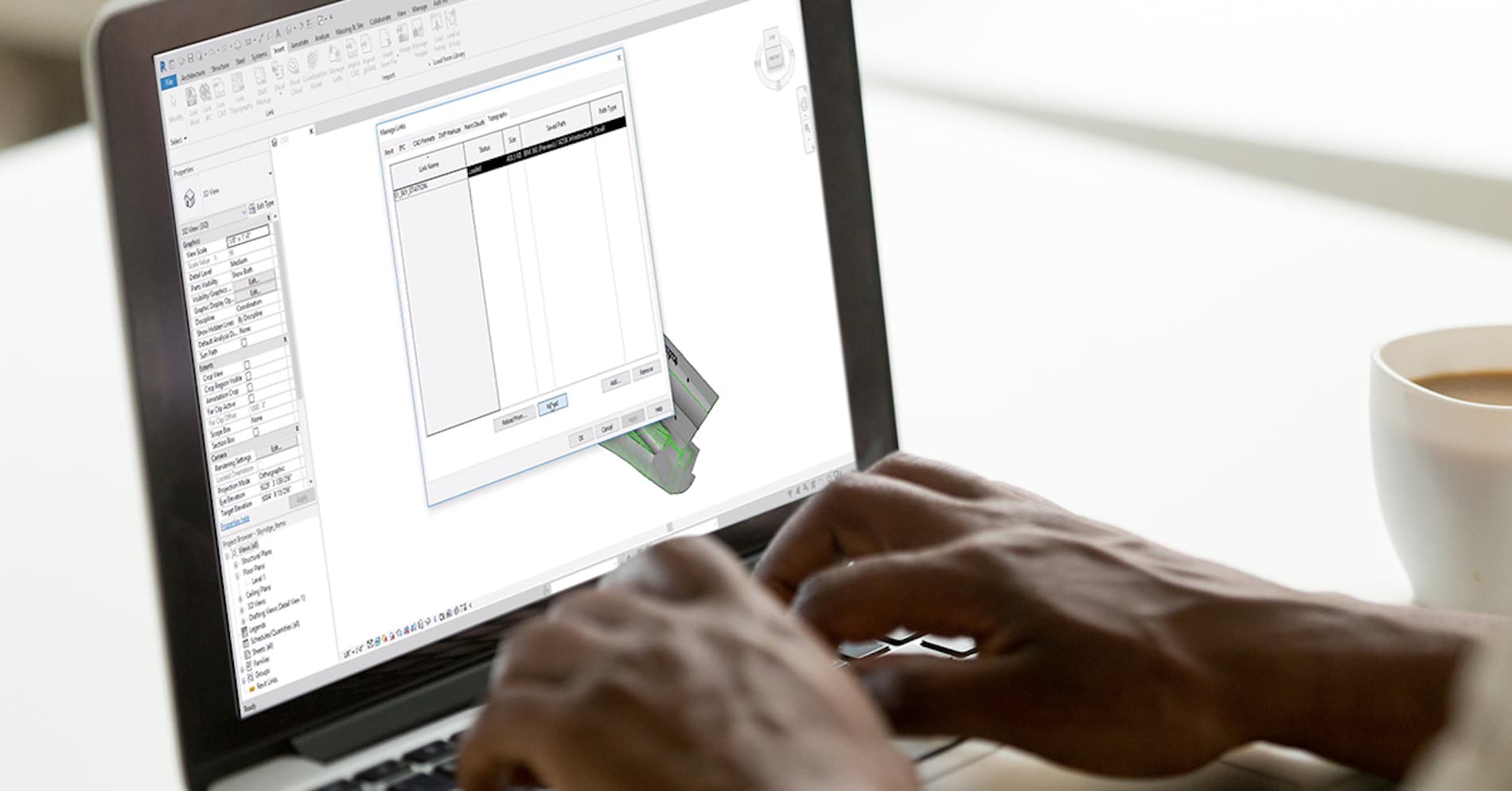
Let’s talk about Revit families. Are your Revit users pulling families from manufacturer websites, then having to spend project time individually reconciling the differences between the parameters used without destroying existing data?
Downloaded Revit family content introduces shared parameters into a project that are often times different from the parameters used in the company’s schedule. These differences often cause schedules to display incomplete or inaccurate data requiring tedious, individual fixes.
BIM Project Suite 2020’s Parameter Jammer uses a two-step process to swap the parameters in the family to reconcile the differences between the parameters without destroying your existing data, saving users time and headaches. The first step swaps parameters that can be safely identified as a match, while the second allows users to map, add or omit parameters that do not need to be swapped.
Parameter Jammer is user friendly, and was designed so that Revit users who are unfamiliar with the family editor can successfully prepare a family to be scheduled; it also:
Uses the schedule to derive parameter needs; and
Allows the end user to push parameters into a non-standard family.
Find improperly displayed elements in Revit with Invisibility Advisor. Part of the BIM Project Suite, this tool can also identify the cause of invisibilty as well as offer useful information and links to relevant knowledgeable articles for each issue.
Common Challenges
Revit users may spend 2-4 hours a week on average resolving object visibility issues
Revit has various ways of finding objects, and users rarely check all
Often invisibility can be controlled by multiple factors and multiple users
Solution – Invisibility Advisor
Invisibility Advisor searches through almost 60 different factors affecting an object’s invisibility
Advice is offered to assist with understanding why the object(s) were not visible
In many cases, an instant ‘Fix’ option is available to resolve the visibility issue automagically
The Invisibility Advisor can remain on screen while you work, so visibility solutions are available at your fingertips
ROI
At even 1 hour per week time savings, Invisibility Advisor can save an average firm $3400/year/Revit user
My friend and customer, Ben Cartmell from Koers & Associates in Parksville, has brought to my attention a method, of which you may not be aware, for working around a limitation within Civil 3D.
The limitation is when a drawing containing Civil 3D structures is XREF’d. The image below shows two viewports in paper space with pipes and structures that have been XREF’d in model space. The structures are annotative and they should be the same size within the viewports, but they are not.
There is an easy workaround for this problem. The file being XREF’d in the example above was saved in model space.
Open the file.
Switch to paper space.
Save.
Reload the XREF and those structures now appear the same size in paper space.
TORONTO, ON, July 8, 2019 – Today, SolidCAD, Canadian Autodesk Platinum Partner and leading technology solution and professional service provider announced a new partnership with U.K based company, NBS, a technology platform for construction specification, standards and model integration via the web.
“SolidCAD is happy to be the first and currently the only Canadian partner with NBS,” said Michael Kugan, President of SolidCAD. “We believe in providing leading technology solutions to our clients, and that means investing both the time and resources into our team so they can provide unique expertise that help streamline our customers’ processes. NBS products will help digitize building specifications, standards and regulations within the construction industry. SolidCAD is happy to offer this new solution and support this product to the construction professionals of Canada and help lead the digital evolution.”
Richard Waterhouse, CEO of NBS, added “We are delighted to be partnering with SolidCAD, to bring digital specification to Canadian construction practices. SolidCAD’s vast knowledge of the Canadian market, high standard of service and deep links with Autodesk solutions made it a natural choice for us when considering a partner for our NBS Chorus platform. Together we’ll be bringing customers the power to write specifications live on any device, collaborate across time zones, and fully integrate their Revit models. This will bring huge benefits in terms of efficiency, reduced risk and speed to market for Canadian construction.”
Over the past two years, SolidCAD has gone through immense growth. From the acquisition of multiple Autodesk resellers across Canada to establishing new partnerships with technology providers across the world, SolidCAD is dedicated to offering the latest technology solutions and provide quality services for all professionals in Manufacturing and Architectural, Engineering and Construction (AEC) industries.”
To learn more about NBS, join SolidCAD and NBS for a webinar on Thursday, July 11 at 10:00 am PST/1:00 pm EST. To register, please click here.
About NBS
NBS has over 40 years’ experience of providing specification tools for many of the world’s most established construction organisations. The NBS Chorus platform brings the power of digital specification to Canadian construction practices of all sizes, enabling them to develop specifications more intelligently and more accurately on any device via the web. Through the 2017 acquisition of Alberta-based Digicon Inc, NBS is able to offer a full suite of content in Chorus for both Canadian Master Specification (CMS) and National Master Specification (NMS) – www.thenbs.ca
Beairsto & Associates Engineering Ltd. (BASE) has been providing surveying and engineering guidance towards the growth and development of the communities they serve since 1963. BASE provides:
Municipal Engineering
Building Design Engineering
Legal Land Survey
Oil & Gas Survey
BASE offers a comprehensive list of services to its clients and is involved in all stages of their projects including: legal, design, construction and as-built survey; drafting services, multi-disciplinary engineering services and project management for all departments, including procurement and site supervision.
BASE is an industry leader, facing typical industry issues related to geomatics workflow and wanted to eliminate bottlenecks in their processes. BASE’s processes were dependent on manual intervention and verification at many stages. Without complete automation, there was a lack of data flow and standardization between software and people. Finally, BASE could benefit from a data management platform for the whole workflow, so as to manage data from all processes. This would automate basefile creation, source/destination updates, consistency, tracking and management. A data management system would improve accuracy not requiring staff to track and check the hundreds to thousands of transactions and files generated on engineering projects.
BASE chose SolidCAD/Cansel because of their extensive experience in workflow optimization in a whole range of geomatics technologies.
Geomatics Workflow Optimization: Beairsto & Associates Engineering Ltd. (BASE) achieves increased efficiency and decreased risk through automation
Project Profile
SolidCAD and Cansel met with the Design and Survey Management team for a discovery session to understand their existing workflows, issues and future goals. Although BASE was doing well with their current manual practices, they needed a new workflow that would increase efficiency and reduce risk.
During the meeting, SolidCAD and Cansel identified three specific opportunities for their current workflow:
(1) Enhanced Integration Between Stages of the Process – Enhancing interoperability resulted in the ability to leverage data through each phase decreased the reliance on manual processes that may risk data loss or misinterpretation.
(2) Reduced Manual Checking and Management – Leveraging interoperability reduced time spent for employees to check and rebuild data value.
(3) Developed Object-Based Design and Stakeout – CAD systems were configured to receive, design and provide stakeout objects for survey equipment. These objects and supporting data are provided to field crews based on standardized stakeout plans making this process as efficient and comprehensive as possible by meeting the business and technical stakeout requirements.
SolidCAD/Cansel worked with BASE to study their current survey, design and stakeout for construction processes along with supporting datasets and comparing to industry best practices. This work involved reviewing existing files, personnel, equipment and deliverables to determine the most effective change management for BASE for immediate and future requirements. In turn, this led to the creation a strategic roadmap eliciting immediate and future requirements within the vision, goals and objectives of the company.
After the initial work, SolidCAD/Cansel worked with BASE to implement a standardized system, workflow and documentation based on industry best practices that integrated with the existing BASE platform. Finally, SolidCAD/Cansel trained staff in the system and assisted BASE staff with pilot projects, post implementation support and strategic planning.
The Results
BASE has achieved more efficiency and less risk by implementing survey methods that tie directly to design objects and output to stakeout objects. This maximizes the use of surveyor’s time in the field, linking survey data directly to model-based design templates for both survey and stakeout. The model based design uses templates to standardize road, parcel and utilities design and outputs survey objects for stakeout. The system is supported by an organized file and database system including automated updates from external sources, such as municipal and provincial and a managed historic library of survey data directly accessible to anyone who requires access.
BASE continues to refine and expand their processes utilizing their standardized platform and strategic roadmap to grow into horizontal and vertical markets. Overall the Workflow Optimization service helped solidfy BASE’s status as a leader in their industry and improved the way they service their clients in Western Canada.
Énergir, Québec's leading natural gas distributor, collaborated with SolidCAD to transition from MicroStation DGN to AutoCAD DWG, enhancing data accuracy, field safety, and interdepartmental collaboration.[...]
The City of Barrie (“the City”) is a municipality located in Central Ontario, just over 100 kilometres north of Toronto. Barrie is in Simcoe County, on the shores of Kempenfelt Bay, which is the western…
Public transportation – buses, trains, subways, and more – have a wide range of complex assets that are both mobile and stationary. Upgrades, expansions, and new assets become intricate engineering projects involving a broad array of[...]
As a collaborative BIM software, Revit enables multiple authors to work within the same project file. However, as projects progress files can grow rather large, often time filling up “extra stuff”. This extra data can cause model performance to slow down or lag, causing models to take far longer to open, save, or close.
Additionally, users may take more time to navigate through this extra information to find the correct view, sheet, content or other relevant data. Some processes exist to alleviate these issues inside of Revit, however they are time consuming, tedious, and incomplete.
Describing the issue
The development of Revit project files comes with a lot of work to maintain a healthy file for continued, efficient user workflows. BIM Managers must keep going through the files, cleaning up all the unneeded information. Deleting views, view templates, filters, unused sheets, link & imported elements from the file. Additionally, reviewing all views, trying to find non-standard elements that users might have created in the file. Finally, checking the model to make sure the users are following best practice of modeling correctly. These tasks and more all take time and must be done regularly to ensure that models do not break minutes before major submittals. The breaking of models, file corruption, or file slowdown may require the stopping of work for repair of a problematic model has cost that is not frequently quantified. Fortunately, there are project maintenance tools available in the CTC Software’s BIM Manager Suite that makes this entire process easy to execute, and significantly reduces model downtime, and stoppages of work.
Workflow Description
The use of Project Cleaner makes efficient use of time in cleaning up garbage views from the project. Leveraging the Import/Link Manager can rapidly allow identification and repair of the imports in the model. Intelligently running Type Swapper can save hours of model maintenance and cleanup of rogue types. Finally, Dimension Checker makes it possible to identify areas in a model where information has been faked to ‘just get it done’, but could be a liability issue, or a model fidelity issue later in the project.
Workflow Steps
Project Cleaner
Allows BIM manager to easily manage unwanted or unneeded views, sheets and schedules in the project without re-organizing the project browser
Removing user duplicated working views can frequently enable purging of unused documentation elements, reduce file size and speed model performance
Using ‘Options’ can enable sorting of views and sheets in meaningful ways to enable rapid decision making about view use and value
Import & Link Manger
All too frequently files are improperly linked or imported into production models
While Revit does allow minimal management of links, there is no easy way to find and fix imported AutoCAD files
ILM is critical to the regular maintenance of models by finding and fixing imports and update link settings in a simple interface
Type Swapper
If a user copies content from other projects or explodes an imported CAD file, many dimension, text, line styles and fill patterns will manifest in project models
Upkeep of these non-standard elements is near impossible manually, but the Type Swapper allows cleaning the model of these non-standard elements by swapping to standard types and purging those that are not wanted
Dim Checker
Sometimes designers and engineers do not feel they have time to properly coordinate modeled object positions
Too frequently this leads to overriding dimension values in very dirty ways, mimicking the days of AutoCAD workflows
Unfortunately, these are rarely found and more rarely repaired
The DIM Checker allows these dimensions strings to be found and reports generated to allow the team to easily repair and coordinate these dimensions where appropriate
The ROI
The manual tasks to accomplish the work described above can take many hours per file, with several files within a single project. Often doing this work manually would require users to stop production and exit a Revit model, thus stopping billable work. The tools on the BIM Manager Suite can frequently be used during users working in production. Simple tasks like tracking down rogue line types can be finished in minutes. When speaking with BIM Managers, we often hear that a 1-hour repair cycle is often needed, and in these times, users are not able to be in the model, limiting production time. If the project has 3-5 people working in the model, then their time is lost during this repair effort. At $150 billable rate, this equates to ~$750 each time a repair is needed on each project. If even 2 projects a month require some attention like this, then $18000/year is thrown away to model maintenance. When using the BIM Manager Suite, often these tasks can be completed in 15 minutes, and users can continue to work in the model, so no production time is lost. This is easily a savings of over $17000. Also, since this can be done more easily, projects don’t get to critical halts due to issues. Preventative maintenance has the side-effect of helping projects run much more smoothly, saving time throughout the entire project lifecycle, and making everyone’s work in Revit more enjoyable and productive.
To download your 14-day free trial of these tools, click here or contact your SolidCAD representative to have a formal orientation on these workflows and related tools.
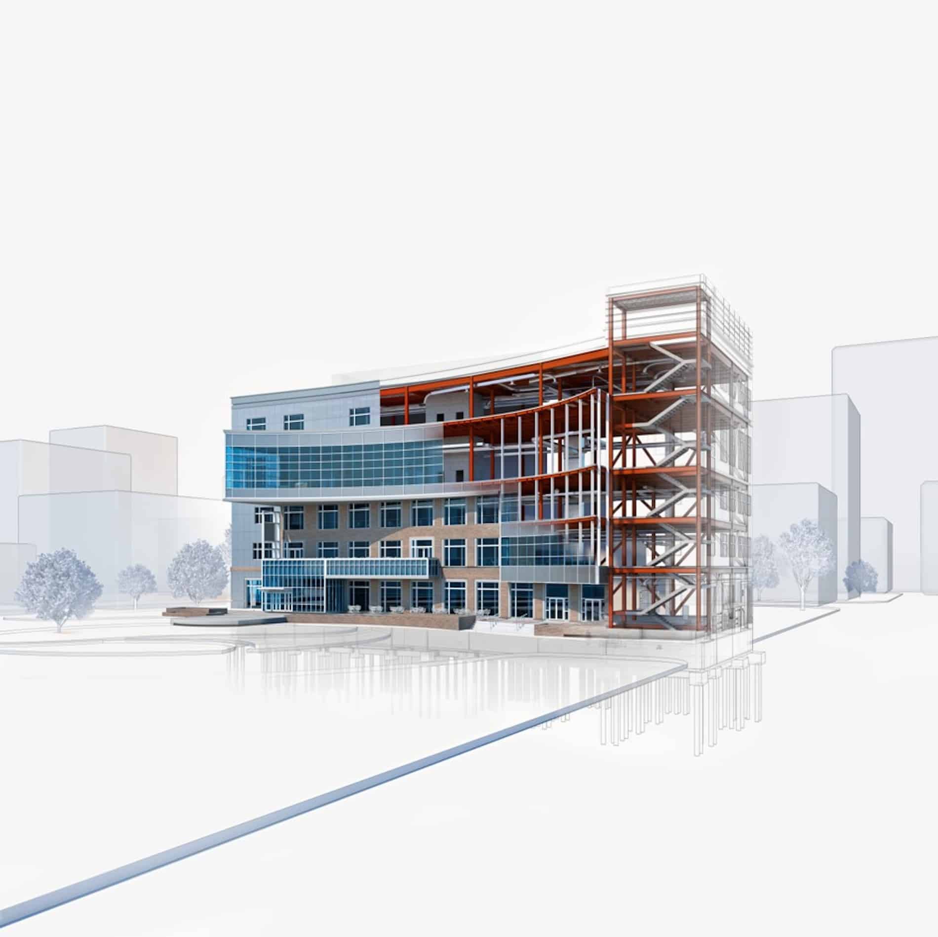
3D visualization is an essential part of architectural illustration today. Renders allow you to communicate your vision and intent to clients and colleagues. This is why models or drawings are often sent out to be professionally rendered. This is an expensive but usually necessary process. However, it is possible to make high quality renders in-house using Revit or through the cloud.
What makes a beautiful render? Like many things, beauty is in the eye of the beholder. It is in the nuance of the materials you select, the lighting, the details you choose to include, and any post-production editing.
Here are a few thoughts on how to start making more beautiful, detailed renders in Revit.
I’ve wrapped them all up in a short video at the bottom of this post.
Materials
Materials are the foundation of every Revit render. They are what gives an element in Revit its color, context, and texture. They are part of the scene and should be adjusted accordingly.
The default color in Revit is grey. Leave the materials on their default setting and when you hit the render button, you will get a series of grey blobs with no information or appeal.
Luckily you can easily change this by adding texture to the material. Look in Revit’s image library or Google JPEG’s or PNG’s with your desired texture. Remember that you can also experiment with attributes like reflectivity and transparency to get the textures looking just right.
Details
It is the details that make a render feel realistic. Buildings do not sit in a vacuum. Neither should renders. The more detail you are able to add to your render, the more more realism there is to your images especially when you work with real-life details. Beautiful renders are photo-realistic. As in photos – trees, people, and other outdoor elements – create the scale and real-life feel. Real pictures are never perfect and a hundred percent clean so neither should your render be.
Sun and Artificial Light
Light is the most important aspects of a rendered image. The lighting of your building should match the lighting of your surrounding. Everything should look like it works and is meant to be together. The shadows should look good and the lux, luminous or wattage should be correct on the artificial lights you are using.
Although you can adjust the exposure afterward rendering you don’t want to be spending all your time doing adjustments. Try to set up the image correctly from the very beginning. This becomes even more important if cloud credits are involved.
Tip: It’s a good idea when trying to render your design to have lights hidden away from the building. This will add some hidden light in the hidden corner or in the back of the camera to give some illumination to the building, just make sure to delete them where they are not needed.
Editing the Render
You can adjust the render after you have rendered it. This is a good way to make minor changes without having to render all over again. You can make things darker or lighter. Change the color make it warmer or cooler. It is sometimes essential to work on some area of the scene to add some dramatic shadow or to correct some texture. You can do this within Revit without having to export to another software like Photoshop and it will hopefully save you time and money..
Many engineers do not realize the power of Revit and prefer to trust the process of designs they have been using for years, such as Excel, manual calculations or their company templates. In fact, they have implemented Revit solely for the purpose of producing construction drawings. They miss the point that Revit can be used for improving performance and collaboration, not only for the drawings to look correct on paper.
In reality, engineers use Revit in conjunction with other third-party software. However, this disconnects the Revit model and calculations, lowers the level of accuracy and results in multiple recalculations.
In fact, Energy analysis is easier to perform in Revit than in any other program. Using Revit for heating/cooling calculations ensures that any changes that were made in the architectural model will be reflected in energy calculations. If you plan on performing energy analysis in Revit, you must define Energy settings, as well as spaces/zones at the beginning of the modeling. To do so you must verify that all spaces are set up with space elements (shafts, plenums, sliver spaces), spaces are added to zones other than the default zone and building/space settings are customized for the project.
Energy analysis runs on an Autodesk Insight subscription. To use it, you must be signed into Revit with a subscription-enabled Autodesk account. To use Energy Optimization for Revit, ensure that the user interface option for Energy analysis and tools is enabled. If not, icons will be greyed out.
Using the Analyze tab > Energy > Optimization pane, you can define Energy Settings, Location, Generate Energy Model, and Optimize Performance:
You can run Energy Analysis in the beginning stages of the project using conceptual masses. However, more advanced analysis for MEP runs on building elements.
When preparing your project for Energy Analysis, you need to make sure you set up Energy Settings properly.
Go to Analyse > Location > Specify geographic location of your project. It is allowing to use a nearby weather station data for Analysis.
Select Architectural link and make sure Type properties is set to Room Bounding.
Go to Architecture Tab > Room & Area > in drop down click on Area and Volume computation. Set computations to Area and Volume. For Heating/Cooling, Energy Analysis and Lighting calculations, you need to calculate Volume for the spaces. When the option is set to Area, Revit will perform faster but volumes will not be calculated. If you notice that space Volume is 0.000, you need to toggle this setting.
Open the Energy Settings dialog. Click Analyze tab > Energy Optimization panel >Energy Settings > Other Options> Change Building Type Data from drop down options.
In the same window, change Building Operating Schedule, HVAC System, Outdoor Air Information, Conceptual Type.
Set Export category to Spaces. MEP Energy analysis model runs on spaces. When it is set to Spaces, Revit passes the following information for use in the analysis: Space object name and number, Occupancy, Lighting, Equipment, and Zone.
Note: you can access Energy Settings from ManageTab > Project information
Change Schematic Types from Building default, which was generated from the information in Conceptual Type. You can override Material Thermal Properties in Categories from the drop down menu to define Envelope elements U-values.
Create Spaces and check that all the spaces are set to room bounding elements – floor, walls, ceiling, roof.
Once everything is set up, you can run the Energy simulation. To do so, go to Analyzetab > Generate.
Revit will send the energy model to the cloud for simulation and analysis. It creates geometry used for energy simulation engines such as DOE 2.2 and EnergyPlus. When the analysis is finished, you will notice a pop-up window telling you the process is completed. You will be able to access the 3D Energy Model View in the Project Browser. You will also receive an email from Autodesk Insight: “Your Analysis is complete. You can access the results on Insight”.
The calculated results will provide you with a total for Energy use. It will build graphs showing how much Energy and what proportion of total Energy is used by each system. Energy and fuel consumption depend on the MEP system chosen for the building. You can visualize results in graphs and compare cost savings between different options.
You can use Autodesk Insight to understand, evaluate, and adjust design and operational factors to improve building performance.
After reviewing results, you can use Energy Optimization for Revit to create an energy model and perform energy analysis with improved settings. You can compare results based on different simulations, print Report to PDF, and compare two different models in the same project side by side. Insight also allows you to collaborate by adding other members to the project. They will have access to the Energy Model and Model Performance.
Today’s demanding business environment is pushing towards more efficient, better quality and cost-effective building design. Energy Modeling and Analysis is a complex and time-consuming process. It is usually done for a Compliance Report, where time and budget allow. With Autodesk Insight, Energy modeling can be done with high accuracy and a high level of precision because it creates an Energy Model directly from an architectural model. Use Energy Optimization for Revit at all stages of design, from schematic design to design development, in order to improve building energy performance. It can be used for projects of any size without straining the budget or delivery time.
Contact us to find out more about Revit for MEP and how we can help you get the most from it.
Panel schedules are an essential part of any electrical design and provide a level of coordination that ensures accurate design and documentation.
Panel schedules can be created before or after circuits are connected to the panel. Once a Panel is placed in a model, a panel schedule is listed in the Project Browser. Using the Analyze >Panel Schedule tool, you can create Panel Schedules using a default template. You can create one or multiple Panel schedules from the Panel Schedule dialog. You can also simply select a Panel in a model and the Panel Schedule tool will become available for this Panel. Keep in mind, you will need to associate each Panel with a Distribution system. This parameter is available in Instant Properties under the Electrical-Circuiting group. The Distribution System is defined under the Manage tab > Electrical settings.
Revit provides 3 main types of panel schedule templates: Branch panel, Data panel and Switchboard.
On the Manage tab, select Panel Schedule Templates and click Edit a Template.
Branch panel
This type of template can only be used with a Panelboard device. Devices that are assigned to the Power system type are associated with a Branch panel template.
You can specify 3 different panel configurations for Branch panels, which can be used for lighting or power systems.
Branch Panel Configuration:
Two Columns, Circuits Across. This is an imperial template, widely used in USA and Canada.
Two Columns, Circuits Down. This is another configuration of an imperial template.
One Column. This is a metric template configuration.
Branch panel schedule with circuits in two columns
To create a Branch panel schedule with circuits in two columns:
In the Edit a Template dialog, select the template type. The template type determines the options in the Templates pane.
If you select a branch panel template, also select the configuration by choosing one of the drop down options.
Select the template to edit and click Open.
The template displays in Edit Template mode. Use the commands on the Modify Panel Schedule Template tab to edit the template. Here you can set the total width of the schedule, number of slots shown as variable or fixed number, format of displaying loads, etc.
Click on Set Template Options
Define General settings
Set General settingsSet Circuit tableSet Loads Summary
Revit panel schedules are highly customizable. You can add Electrical Equipment, Electrical Circuits, and Project Information categories to a panel schedule template. For example, you can add electrical equipment and project information to the header and footer parts. Only electrical equipment parameters can be added to the loads summary. Circuit parameters are automatically pulled to the circuit table part from the model. You can also insert a Notes parameter in the template so that the Notes information can be entered and saved in the panel schedule.
Modify Panel Schedule Template
You can modify the Panel Schedule Template in order to customize it to your company’s standards. Use the commands on the Modify Panel Schedule Template tab to edit the template.
• Remove a parameter – select a cell, then click Remove Parameter. The column is cleared of parameters.
• Combine parameters – select a cell and click Combine Parameters.
• Freeze or unfreeze the height and width of all rows and columns – click Freeze Rows and Columns. You can continue to resize frozen rows and columns using Resize Column and Resize Row, but you are prevented from resizing them using grips.
• Insert a column – select cells, then select either Left of Selected or Right of Selected from the Insert Column drop-down menu.
• Insert a row – select one or more rows, then select either Above Selected or Below Selected from the Insert Row drop-down menu.
You can insert text notes in Schedule Header Notes and Schedule Circuit Notes. These are instant family parameters. They can be edited from the Property palette or from the Panel schedule itself. However, if you just type text instead of associating it with a Notes parameter, this text will be lost when you are updating the schedule.
Data panel
This type of template can only be used with a data panel device. The primary purpose of a Data panel is to identify circuits and data outlets and associate them with telephone numbers. Data panels can be connected to anything except power devices. Typical devices connected to a data panel include telephones, fire alarms, and security devices. Data panels display a single circuit column.
Data panel schedule with one circuit column
Switchboard
This type of template can be used with a switchboard. Switchboard schedules display information about the Switchboard and the connected Panelboards or other devices.
Switchboard panel schedule with one circuit column
You can customize Circuit Tables for Switchboard panel schedule.
Circuit Tables options for Switchboard panel
As you can see, you have a lot of flexibility in producing Panel Schedules in Revit. Using the Rebalance Tool you can redistribute loads with one click in order to make the loads as equal as possible on each phase. You can move circuits up and down within the Panel Schedule without effecting any other circuits. You can assign open slots in a panel as spares or spaces. Also, a spare, space or specific circuit can be locked/unlocked to the slot. You can create multi-pole circuits by grouping a single pole circuit and spare together.
You can change the circuits description, as needed, from the Panel schedule. This allows you to create a Schedule Template which will comply exactly to your company standard or create a unique template to match a client’s standards. It will make creating and managing electrical systems and schedules in Revit easy and efficient, saves design time and reduces possibility of error.
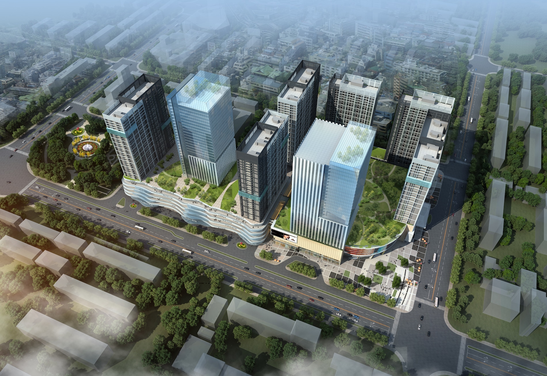
If everybody is so proficient with the change to a BIM process, then why aren’t building projects embracing it more widely? Why aren’t those firms who have embraced it finding the efficiencies that it promises? Why are our buildings not being constructed with less problems? Most importantly, why are those people who build those buildings still not convinced that the move to BIM has improved the quality, capability, efficiency and functionality of their products?
BIM has been around for over 15 years and still many architectural firms are struggling with how to actually leverage its potential. Engineering firms are not utilizing the information in the data-rich models being created. Contractors are spending valuable time remodeling the digital information created by their design teams so that they can utilize them for their purposes. Finally, these models are not of much use to the owners and even more work needs to be done for them to get a true digital repository of the structures they have created.
What has gone wrong? Why can we not create a true digital model of a building that can be used for design; then passed onto production of construction documents; then passed onto the contractor him/herself to build and extract useful data from; and finally passed to the owner to utilize throughout the building’s life-cycle. Along the way, why isn’t this data-rich model used for a myriad of additional benefits? A true building information model should exist throughout the life of a building.
The answer is that WE CAN! The secret is that all of these participants have to want to work together to achieve a set of common goals. The only person who can define what these are is the person paying the participants; yet that person does not have the experience or knowledge to do what is necessary. Until we can get together as one team pulling for that elusive set of common goals, the building process and the resulting building will be a disparate set of activities producing a result that reflects that lack of cohesiveness.
It is time that we got together and came up with a better way to use BIM so that everybody in the process can benefit.


_hr")

")