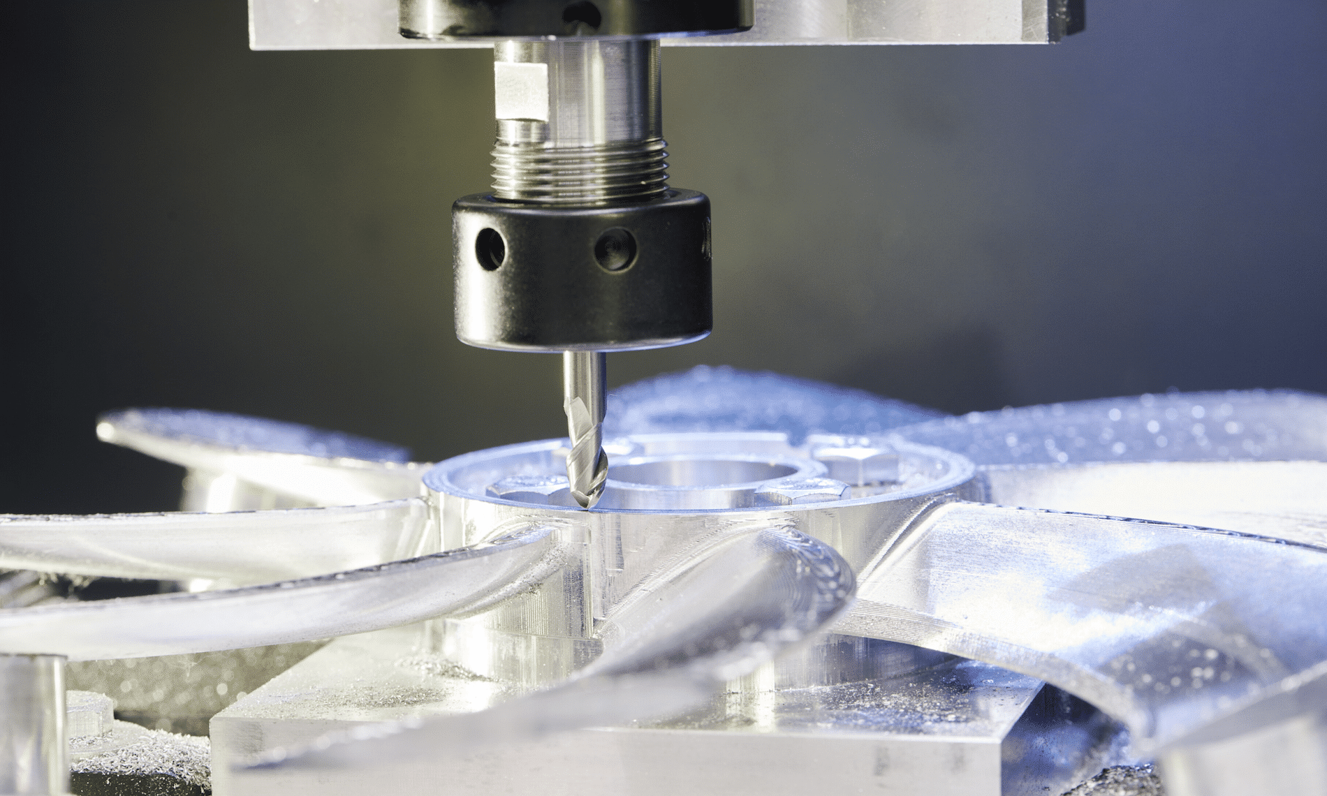
Do you know about Adaptive Clearing? It’s the intelligent roughing strategy at the heart of HSM CAM that has changed milling forever. Increase your profitability by getting to near-net-shape in a single, highly-efficient, tool-sparing operation.
Curious about the hype around Autodesk’s HSM CAM? And now you’re looking for more information and possibly a demonstration? Well, you’ve come to the right place! SolidCAD is not only Canada’s biggest reseller of Autodesk manufacturing solutions, but also the only Canadian Autodesk reseller with a dedicated team of CAM specialists.
HSM CAM is the comprehensive and powerful CNC programming add-on for Inventor (Inventor CAM – included with a subscription to the Product Design and Manufacturing Collection ), Fusion 360 (Fusion 360 Manufacturing – built into Fusion 360), and even SolidWorks (HSMWorks – included with a subscription to Fusion 360).
Also, try our SolidCAD universal milling post-processor, compatible with a wide variety of 3-axis, 4-axis, and 5-axis machines that accept FANUC-style G-code. This open-source post-processor generates nicely-formatted NC code, and is chock-full of features to make it as flexible as possible. These features include:
Safe restart feature after M00 program stops
Automatic date and time stamp function
Tool table feature in header
Operation name, tool name, and cycle time at top of each operation
Activation of accumulated pecking depth feature for G73-style drilling
Activation of the Manual NC code pass-through feature
Property to toggle between 3-axis / 4-axis / 5-axis configurations
Property to set maximal spindle speed
Property to toggle tool preload on/off
Property to toggle rigid tapping on/off
Property to assign an M-code for rigid tapping
Property to toggle between G54-G59 and G54.1 P1-P300 work offsets
Property to toggle between G28 and G53 retracts
Properties to set M-codes for 4th and 5th axis brake lock/unlock functions
Property to toggle on/off the output of rotary axis positions at every operation
Property to toggle on/off the output of M01 optional stops at tool changes
Property to toggle on/off automatic spindle gear changes
Property to set a spindle gear change crossover speed
Property to toggle between French and English for the output of comments and messages
Property to toggle on/off lowercase support for comments
Property to set the rapid rate used for operation time calculations
Property to toggle on/off the automatic creation of sub-programs for patterns
Property to toggle between 4 digit and 8-digit program IDs
Property to toggle on/off the output of the tool list in the program header
Property to toggle between relative or absolute coordinates for IJKs
Property to toggle between automatic tool changer or manual tool changes
Property to toggle between M30 and M99 for program termination
Property to toggle between returning to home or going to parking position at program end
Properties to set X- and Y-coordinates for parking position
Property to convert from feed expressed per min. to feed expressed per second
A few years ago, Autodesk introduced context-sensitive radial menus called Marking Menus, in Inventor. These menus provide a quick and visual way for users to select the most commonly used commands in each environment. Over the years every-day users have no doubt become quite familiar with these menus and the available commands, but did you know you can customize it?
By default, Autodesk has placed what they believe to be the most common commands in this radial menu however, you know as well as I do that from company to company and even desk to desk, everyone uses Inventor differently. The following are the quick and easy steps to customize this menu.
How to do it:
On the Tools tab in the Options pane, the “Customize” button will open the dialog box that lets you modify the 8 commands in the radial menu for a given environment and associated sub-environment. From 2D Sketch to Weldment and everything in between, you can put your favourite commands right at the tip of your mouse pointer.
Choose the environment and sub-environment you wish to customize the menu for. Next, select one of the eight radial menu options that you want to change (in this example we are changing the “Pattern Component” command in the standard Assembly environment).
In the menu on the right, search or scroll down to the command you want to add and simply click on it to replace the selected option (iProperties, in this example). It’s as easy as that!
A
lso; starting in 2018 Inventor began giving users the option to migrate these (and all other) custom user interface settings when you upgrade to newer releases. So, you no longer need to worry about starting from scratch!
Why is it called the “Marking Menu”?
In addition to customizing where your favourite commands are on the right click menus, did you know you can also right-click-drag to the command, without ever actually seeing the menu? The pointer will create a “mark” as you drag your mouse to the location of your desired command, as shown below. This will require some practice but could become quite handy over time when the location of the commands in the radial menu becomes second-nature.
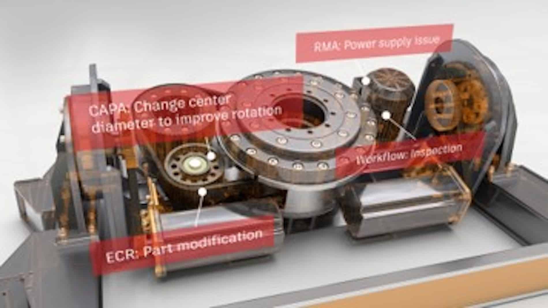
This is the third in a three-part series of Fusion Lifecycle videos. In this video, we will focus on Change Management with a specific focus on Engineering Change Orders.
In the previous video, we saw that the Bill-of-Materials was automatically extracted and transferred to Fusion Lifecycle for additional analysis, modification, export and so on. At a future point in time, someone may recognize a problem with an item in the Bill of Materials and wants to initiate a change. In Fusion Lifecycle, they can log a Problem Report. The Problem Report flows through a structured workflow becoming an Engineering Change Request(ECR) and then an Engineering Change Order (ECO).
When the ECO is approved, Fusion Lifecycle pushes the information back to Vault, where the impacted assembly is changed to a Work-in-Progress state. Designers can then make the necessary design changes and Release the revised assembly.
This is the second in a three-part series of Fusion Lifecycle videos. This video, will focus on the Bill-of-Material transfer from Autodesk Vault Professional to Autodesk Fusion Lifecycle.
Vault Pro and Fusion Lifecycle can be integrated allowing data to move between the two systems. When Designers and Engineers have completed their work in CAD and Vault Pro, they will Release the assemblies. The Bill-of-Materials is then extracted from Vault and transferred to Fusion Lifecycle as an Items BOM. In Fusion Lifecycle, the BOM can be managed by adding or removing items. When complete, the BOM is advanced to the Approval Stage using Fusion Lifecycle’s Bill of Materials Management capabilities.
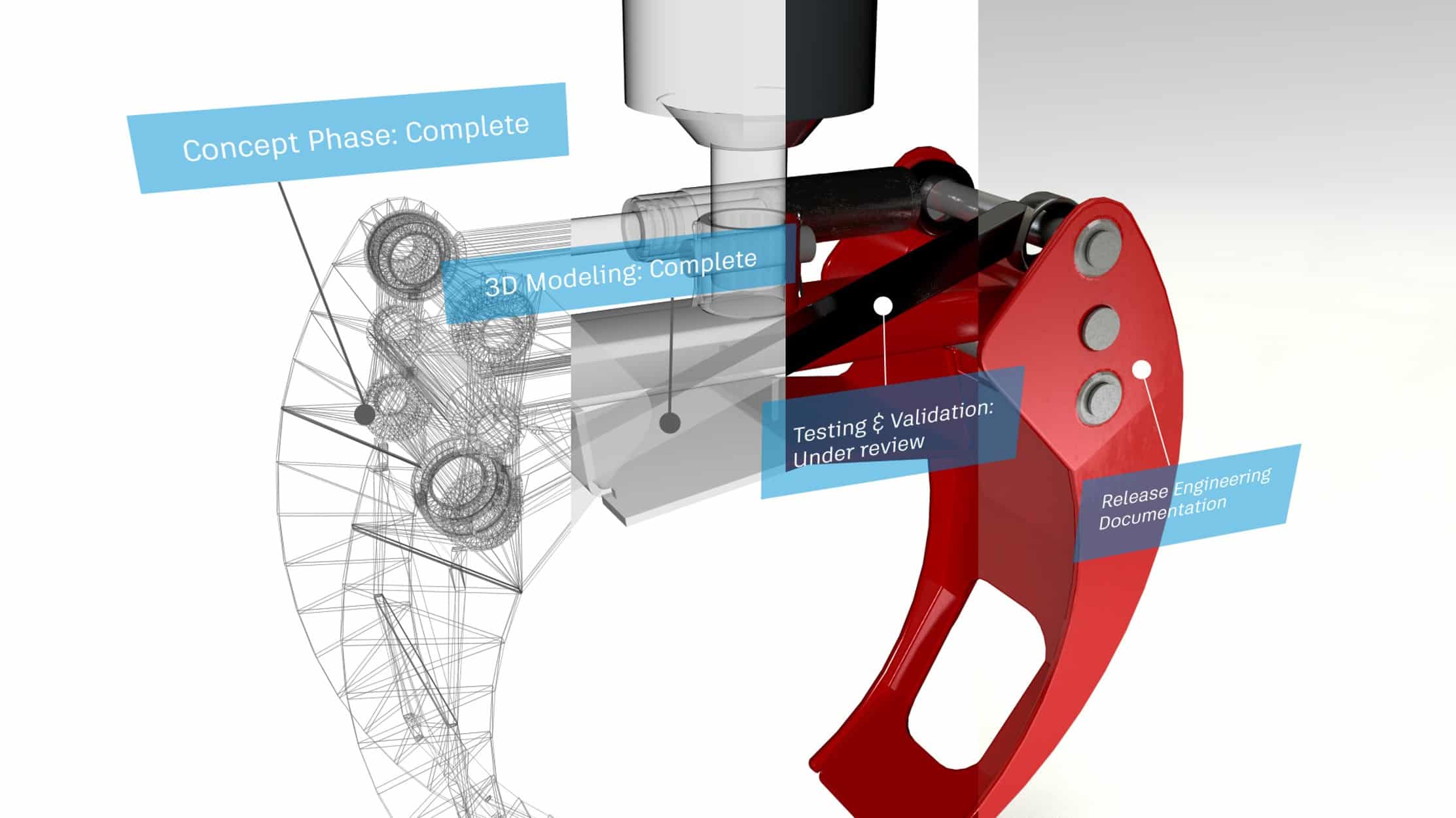
This is the first in a three-part series of Fusion Lifecycle videos. In this video, we will review the New Product or New Project Introduction process in Fusion Lifecycle.
Fusion Lifecycle and Autodesk Vault Professional can be integrated to streamline the Project creation process. In our example, we will begin by creating a project in Fusion Lifecycle. Upon approval, Fusion Lifecycle will then automatically create that project in Vault, complete with our defined folder structure.
In case you were unable to attend SolidCAD and CTC’s webinar last week here is what you need to know…
Shawn Zirbes, a Guru for everything CTC, uncovered how the BIM Project Suite allows Autodesk Revit users to automate routine tasks, manage large numbers of content files, generate database information and much more in a lot less time, all within the Revit environment.
BIM Project Suite is meant for everyday users of all skill levels and used by firms of all sizes. To learn more about the some of key functionalities of the suite, watch the full webinar on our YouTube Channel.
DIALOG believes that their passion for design should improve the wellbeing of our communities and the environment they share. DIALOG’s multi-disciplinary team of 700 includes architects, interior designers, structural, mechanical and electrical engineers, urban planners, and landscape architects. They practice across the US and Canada from studios in San Francisco, Vancouver, Calgary, Edmonton and Toronto.
DIALOG’s multi-disciplinary team provides their clients with a comprehensive and collaborative approach to design. Their team can overcome the challenges of increased complexity within design and planning with their diverse perspective and expertise for greater efficiency.
For years, DIALOG has worked on various projects including: designing for urban vibrancy, health and wellness, transportation, education, arts and culture, residential, retail, and commercial. Their vision has always been to think outside of the box and adopt new design technologies that will improve digital collaboration, improve communication among their team and clients, and provide quality services on any project.
HH Angus is an employee-owned, independent consulting firm of engineers, technical specialists and project managers. Together, they create innovative solutions for their clients’ most complex challenges to expand what is possible for a better future.
Oneira Corporation, An EPCM* Company, Is A Leading Engineering And Technology Company Providing Industrial Process And Solutions Based in Toronto, Canada, Oneira has more than 30 years of experience working with global leaders in the Specialty Chemical, Chemical, Oil…
Cumulus Architects Inc. is a multidisciplinary architecture and design firm located in Toronto, Ontario. Cumulus is founded on the principles of team-based design and integrated project delivery with the belief design intelligence results from broad…
A little tip today. Have you ever zoomed out within a profile viewport and your surfaces and alignments are not there? The two viewports shown below are nearly identical except the one on the bottom doesn’t display any Civil 3D plan objects, such as the surface and alignment. Why is this? No, layers are not frozen or off in the lower viewport.
Civil 3D has its Plan Production feature which automates the creation of Paper Space layouts, typically for plan and profile construction drawings. The way it has been implemented is that your drawing template (DWT) will contain a sample paper space layout containing pre-configured viewports. And those viewports are required to have set a specific property called Viewport Type.
In the image above, the top viewport is set to Plan and the bottom is set to Profile. When the viewport type is set to Profile, Civil 3D plan objects such as surfaces, alignments, and corridors are not displayed. This is presumably to conserve performance, but if you’re unaware of this feature, it can be confusing.
Bluebeam has released their latest update for their flagship PDF markup tool, Revu. Please see this link to learn more about how to update your installation, and then click here to find out which defects have been addressed.


 A
A