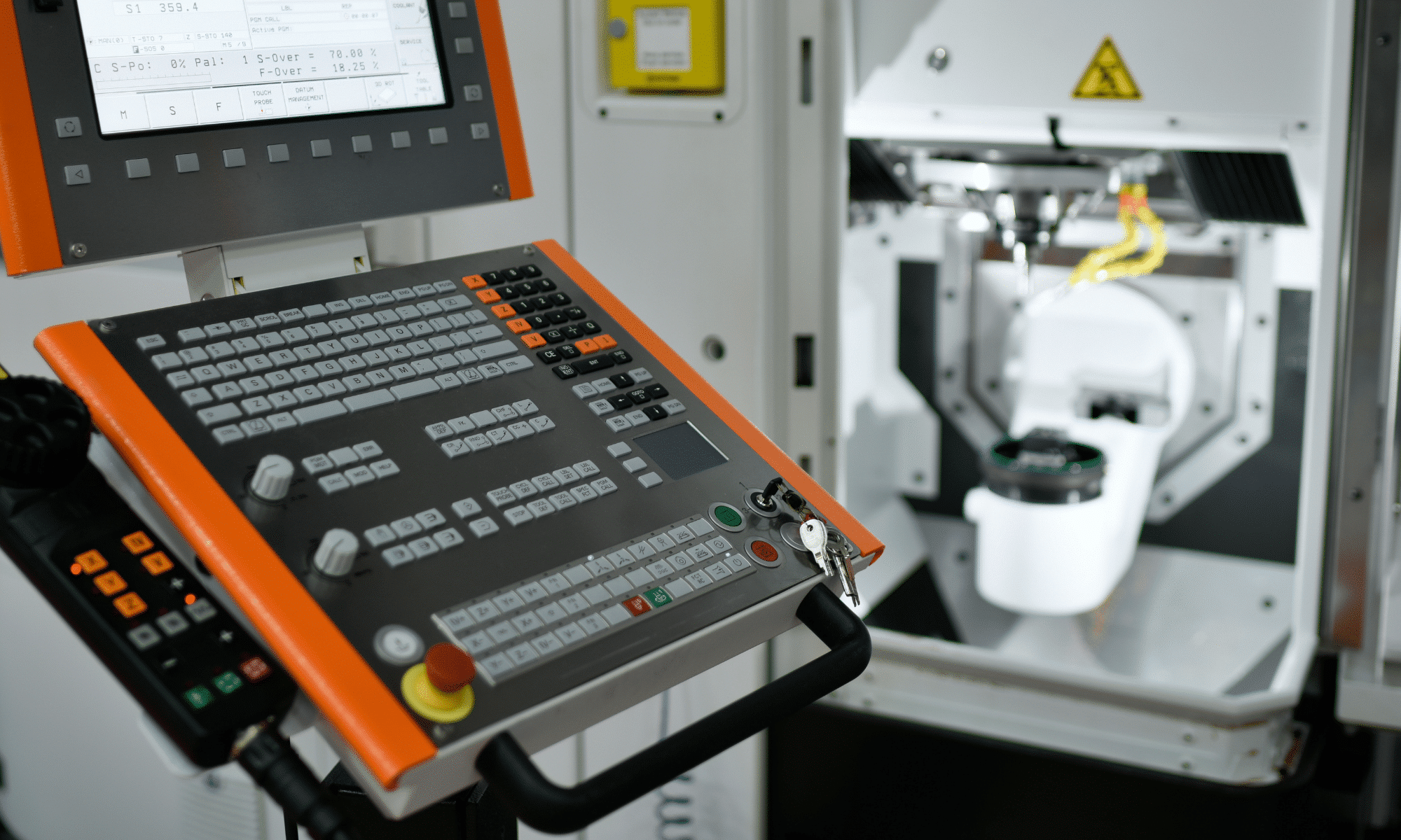
• The new Rotary machining strategy in Fusion 360 CAM is a thing of beauty!

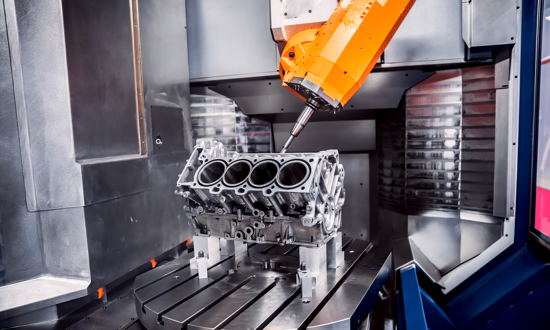
    Last month, I wrote that a lot of improvements and new features had recently been built into Fusion CAM. One of these is the Rotary multi-axis 3D milling strategy, which has been a very long time in coming. What this is, is a strategy for mills or mill-turns that makes use of a rotary axis to 3D-machine around a part with a ball-nose cutter. The cutter is always kept pointed towards the center of rotation. Machining can be performed milling-style, with a back-and-forth toolpath along the axis of rotation and successive incremental steps (stepover) of the rotary. Better yet, machining can be performed turning-style, front-to-back (or top-to-bottom) with constant motion of the rotary and a specified stepdown per revolution. The centerline of the tool can be slightly offset (if your machine allows it) so as to stay off the center of the cutter.

    Well, I can say that the wait has paid off. We recently had a chance to put this new strategy through its paces with the help of our good friends at Dery’s Manufacturing of Regina using their big Nakamura WT-300’s mill-turns. The results were very impressive. We confirmed that using this strategy turning-style is particularly efficient, as it allows to take as big a depth-of-cut as needed and to potentially shape the part in a single pass.

    This new strategy clearly fills an important void. It will be appreciated in a variety of settings, including routers with a 4th axis mounted to the side. And it will be appreciated by users who have struggled in the past with “textured” or “3D” revolved parts, including STL models.

    Rotary is available as part of the “Manufacturing Extension” for Fusion 360, which includes other useful additions such as the very-powerful Steep-and-Shallow 3D strategy, borrowed from the all-mighty Powermill. The Manufacturing Extension costs 125 Cloud Credits ($125 USD) per month to access.

    Like many of the other recently-unveiled goodies, Rotary is unfortunately not available for Inventor CAM. That’s too bad since Rotary is an essential strategy that deserves to be included in the base offering of Fusion CAM, as well as in Inventor CAM and HSMWorks. I encourage you to vote for this on the Inventor IdeaStation. That being said, if you are an Inventor CAM user, your Product Design and Manufacturing Collection gives you access to Fusion. If you are an HSMWorks user, you as well now have free access to Fusion 360. And Autodesk has been working very hard of late to improve data exchange between Fusion and both Inventor and SolidWorks, in order to allow you to work with Fusion in parallel with these legacy platforms. Indeed, expect that later this year, Fusion will be able to retrieve CAM toolpaths saved inside an Inventor file.

    What’s new in turning? A lot!

    I mentioned in my last entry that Turning saw some important (and overdue) improvements of late. Indeed, you may have noticed that the Turning/Profiling function has been broken into a dedicated roughing strategy and a dedicated finishing strategy, for much more control and to allow for output of canned cycles. This happened around the middle of last year for Fusion, and a bit later for Inventor CAM.

    What you may not have noticed, however, is a myriad of small but very-welcome improvements everywhere else too. It’s a long list, and I refer you to Marti Deans’ excellent coverage here: https://www.autodesk.com/products/fusion-360/blog/turning-updates-fusion-360/

    Also, as I said in my last post, this is apparently just the tip of the iceberg. Turning experts have joined the Fusion development team and are hard at work implementing more functionality and innovative technologies (like Adaptive Turning). I hope to see a lot of the power of PartMaker ported to Fusion CAM!

    Tons of new goodies for Fusion 360 CAM

    Since I last wrote here, there have been big, big changes to Fusion CAM (excuse me: “Fusion Manufacturing”). These changes range from completely new (and it needs to be said, very useful) machining strategies, to significant progress in the implementation of probing technology, to new love for turning, and to subtle but much-appreciated improvements to the user-interface.

    The biggest changes are contained within the Manufacturing Extension, a new subscription add-on for Fusion CAM. The idea is that while Fusion CAM (and Inventor CAM and HSMWorks, for that matter) is a modern and very competent CNC programming solution that can make short work of most jobs at a VERY attractive price, there are some customers that require still more power and that are willing to pay a little extra for it. Mold makers are a good example. In the past, the limited multi-axis toolpaths of Fusion CAM did not quite meet their needs. With the new Steep-and-Shallow strategy as well as toolpath trimming / direct editing (both technologies gifted from PowerMill), that has all changed. The Manufacturing Extension also opens the door to surface inspection and on-machine verification, a very hot button for anyone trying to increase efficiencies and get an advantage. Throw in automatic hole recognition technology (thanks, FeatureCAM) and a new Rotary multi-axis 3D milling strategy (this one is all Autodesk), and there is something for everybody. How much for these new goodies? 125 Cloud Credits ($125 USD) per month, month-to-month.

    And those other improvements? How about a new tool library interface? The old one definitely was a little clunky. And for those of you who make extensive use of user-templates to capture their best practices (why isn’t everybody?), how about a new interface that will allow you to sort and better manage everything?

    I haven’t talked about turning yet… It can be said that while Fusion CAM  / HSM CAM has traditionally been a competent turning solution, most of the R&D over the years has gone into making it a premier milling solution. But a dedicated turning team has now been brought into the development team, and turning is now getting the love it has always deserved. In my next blog, I’ll list all the recent changes (it’s a very long list of small but significant changes). What’s more, we are promised many more such improvements throughout the year, including something called Adaptive Turning that sounds very promising.

    Please note that the Manufacturing Extension is free to use right now through June 2020. So, by all means, give it a spin! Several of the other new features are available through the preview mode: just activate what you want under Preview Features in your Preferences; everything is quite stable.

    Now, it is quite apparent that Autodesk is turning Fusion into its premier CAM solution. That’s great news and we welcome all the improvements to an already-great CAM. However, if you are a user of Inventor CAM (or HSMWorks), don’t hold your breath for things like Steep-and-Shallow. Instead, Autodesk would rather you fire up the Fusion 360 entitlement included with your CAM. And to make it easier to use two platforms in parallel, recent changes now allow Fusion to play extremely well with Inventor and even SolidWorks.

    Sharing is Caring

    In todays manufacturing world there is a bigger demand on sharing data with all stakeholders outside your company.  This could be your supplier, buyer, manufacturing team and they could require viewing the drawing to the 3D model that you create.  Using Autodesk Vault you can created a shared view for your outside stakeholders and value chain.  Autodesk provides this as a free viewer, markup and comments, all they would need to do is sign up for a free Autodesk account.  Also Share View is a great tool to use internally as well to do digital markups and collaboration outside the engineering department.

    To use Share View simply log into Autodesk Vault and find the model or drawing you would like to share and right click and select Share View:

    You may be prompted to login using your Autodesk account, once you have logged in the Create a Shared View dialog box will prompt you to enter a name:

    Enter the name you would like and then click on Share, and it will start to process the shared view.

    Once complete a Share View Complete Dialog will display that it was uploaded successfully and it will give you a copy link and view in browser option.

    Copy Link – This is the link you can email to your stakeholders for them to open and view online.

    View in Browser – this will open the shared view in your browser for you to view.

    Clicking on View in Brower it will launch the Share View online:

    This view will only be available for 30 days on Autodesk Viewer.  Only users who are invited though the link or when selecting share will have access to the model or drawing.

    Once singed in users can markup, add comments and when clicking on share, it will send the users in Vault a notification that someone has made a comment on the drawing.

    To make a comment simply select comments to type a comment directly.  Anytime you click on Markup the markup changes will be saved on the comments tab when you select Post.


    In Vault client to view the comments or markups make sure that Shared Views Panel is turned on.  If not turned on simply go to View > Shared Views and make sure there is a check mark beside Shared Views:

    In the Shared Views panel the comments and markups will be shown:

    To make a comment back simply click on Reply and it will take you back to the Autodesk Viewer to continue the collaboration between your company and stakeholders.

    As you can see getting data to correct users at a timey manor is critical in todays business.  Autodesk Vault Professional and Shared Views enables you to connect the value chain and make sure everyone has the data they need.  Also, Autodesk viewer is not just limited to Inventor or AutoCAD drawings and models if you go directly to viewer.autodesk.com you can sign into your account and upload the following files for collaboration:


    Remember Sharing is Caring and happy collaborating!!

    Dynamo for Autodesk Fusion 360 – Made Simple

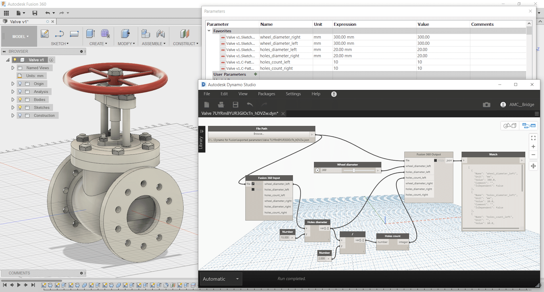
    Dynamo Studio is typically associated with Revit; however, it offers a fantastic platform for algorithmic-driven design and easy parameter manipulation in Fusion 360. It also features great T-spline and surface support for complex geometry creation, for those wishing to bring a degree of parametric control to their surfacing with ease.

    The add-in supports a bi-directional data exchange between Fusion 360 and Dynamo Studio, allowing users to create visual logic for Fusion 360 parameters update. It can be downloaded here: https://apps.autodesk.com/FUSION/en/Detail/Index?id=74731490955641349&appLang=en&os=Win64

    It provides an ability to use a visual editor environment to modify Fusion 360 model parameters, view and use them in complex logical graphs. Fusion 360 parameters will be automatically updated from Dynamo Studio using custom input and output nodes.
    Dynamo for Fusion 360 Supports Dynamo Studio 2017 version: 1.1 – 1.3.

    The benefits of using Dynamo with Fusion 360 are:

    • Very complex and rapidly reconfigurable T-Spline surfacing is
    • Parameter driven components can be modified live using sliders to adjust
    • Parameter driven components can have logic integrated to link different parameters and make automatic adjustments according to conditional
    • Parameter driven assemblies can be modified live and can adapt if setup
    • Parameter driven assemblies can have logic integrated to link parameters from different components to respond to changing geometry according to conditional

    One of Dynamo – Fusion 360 Workflows is called “Synchronous workflow”. It is directly manipulating parameters listed in the parameter table in Fusion 360. This can enable rapid reconfiguration of assemblies and components by using sliders, or logic can be incorporated to describe relationships between geometry. If you have not tried, here are some simple steps to try:

     Step 1: Create a simple Fusion part with some name parameters as shown:

    Step 2: Save and name the part as “Dynamo-Fusion”

    Step 3: Go to Tools -> DYNAMO FOR FUSION to run Dynamo


    Dynamo will create a same name parameter file with extension “.json” that contains all extracted parameters from Fusion 360 part and stored under:  C:\Users\ (your username) \AppData\Roaming\Autodesk\Autodesk Fusion 360\API\AddIns\Dynamo for Fusion\exported parameters\

    Step 4: In Dynamo’s search bar, search for “output” and insert “Fusion 360 Output” node. Repeat search for “Slider” and insert “Number Slider” node.


    Step 5:
    In Dynamo, connect File Path to “Fusion 360 Output” and “Number Slider” to any parameter and set Min, Max and Step. Use the slider to size or adjust the features.


    If you would like to manipulate other parameters, then just add more sliders. Simply select the slider node and use Ctrl+C to copy and Ctrl+V to paste it. After that you can customise each slider values (Max, Min, Step) and connect it to any of the parameters and watch the part update. You can even connect a slider to more than one parameter (i.e. to make a square cut).

    Using Dynamo with Fusion360 can be fun and simple. Try it and have fun with Dynamo for Fusion 360.

    Frame Generator End Caps in Inventor 2020

    In the 2020 release of Inventor, the Frame Generator Design Accelerator received a number of minor enhancements as well as one of significance that likely has users asking how they ever lived without it. You can now create and insert end caps to a frame member within Frame Generator.

    Here’s how:

    First; you must have the Custom Content Center Library installed in order to use this feature. Learn how to do that here. Once you have frame members ready for end caps, follow these steps to quickly create and add the components:

    (1) Select “Insert End Cap” on the Frame panel of the Design tab within your assembly;

    (2) Select the end faces of the members you wish to apply end caps to.

    (3) Choose the placement: Inset, or outward

    (4) Choose the profile style: Filleted, Chamfered, or Sharp corners

    (5) Enter the Chamfer/Fillet size (if applicable), Thickness, Inset (or Offset) distance & Rotation angle

    (6) Select the desired part properties, then OK (or “+” to add additional end caps for different tube profiles without exiting the property panel)

    (7) The end caps are created as members of the frame assembly and the file naming can be controlled in the same way (using “File Naming Defaults” in Application Options). Inventor recognizes identical members upon creation and reuses the end cap files where possible, rather than duplicating them.

    End caps can be edited or reused like frame members, using the right click menu in the model browser (“Edit with Frame Generator”)

    HSM CAM Tips and Tricks: Equation-Driven Parameters

    I will be publishing quick Tips and Tricks regularly to help make you more productive and to capture your best practices.

    One of my favorite such tricks is using “smart fields” or equation-driven parameters.

    Virtually all fields in the CAM interface that accept numerical values can also accept equations that reference constants or reference other parameters/fields. Right-clicking on the field and selecting “Edit Expression” brings up an input box wherein you can enter a constant value or build at equation. Once you are done, right-click again and select “Make Default” so that this change is remembered the next time you use this machining strategy again.

    An example where a constant might make sense is plunge feed rate for operations other than drilling operations. Indeed, this is an approach speed that is largely independent of tool type or size. Perhaps you want this to always be a nice and slow 20 IPM until the program is proven safe. Stock-to-leave is another parameter that could be set to a constant.

    Referencing another parameter introduces more power. For example, several parameters can be made dependant on the cutting feed rate.

    Indeed, you can set the lead-in and lead-out feed rates to vary proportionally with the cutting feed rate. Similarly, the reduced feed rate for inner corners specified under “Feed Optimization” should also vary proportionally with the cutting feed rate defined under “Feed and Speed”. An expression referencing cutting feed rate would look like this:

    (tool_feedCutting * 0.5)

    Several parameters can be made dependent on the tool diameter. Indeed, stepovers and stepdowns are prime candidates, as are lead-in/lead-out segment definitions, spiral entry diameter, and stock-to-leave values. An expression referencing tool diameter would look like this:

    (tool_diameter * 0.5)

    Finally, expressions can contain logic and can combine the two approaches described above.

    For example, stock-to-leave might be controlled by an expression that considers tool diameter, but defaults to a minimum value below a threshold tool diameter.

    (tool_diameter >= (.250in) ? (tool_diameter * .05) : (.010in))

    Expressions can be as complicated as you can make them. They just need to respect JavaScript syntax.

    A complete list of parameters that can be used in expressions is found here: https://airtable.com/shrggXZ4wpuGUiN3w/tblJ9PHav1NwMmqMz/viw09jWqXAR0JmPPM?blocks=hide

    Investing two hours into setting up expressions for various machining strategies can go a long way towards capturing your best practices and automating HSM CAM, resulting in increased programming consistency and decreased programming time.


    SolidCAD Earns Autodesk Fusion Lifecycle Specialization

    TORONTO, ON, February 11, 2020 – SolidCAD, Canada’s largest Autodesk Platinum Reseller and professional services company, has been awarded the Fusion Lifecycle Specialization allowing them to provide clients with industry leading product lifecycle management (PLM) tools, training and support.  To earn this recognition, Autodesk partners must demonstrate extensive product knowledge including successful implementation, complete all Autodesk’s industry-specific certification exams and develop expertise and skills with the Fusion Lifecycle platform.

    With this new specialization, the SolidCAD team will help address common challenges within the manufacturing industry and provide solutions to optimize collaboration and improve data management across all departments and workflows.  The team will offer consulting and training services to help manufacturing clients automate processes, manage Bills of Materials (BOM), implement a collaborative environment for product changes and generate the ability track product data throughout all revisions and stages.

    Kirk Givens, Director of Americas Channel Sales for Autodesk, stated, “SolidCAD has been and will continue to be a strategic partner to our customers in Canada.  The Fusion Lifecycle Specialization is testament to Autodesk’s confidence and trust in SolidCAD’s ability to help customers navigate the challenges they face every day and thrive in a competitive business environment throughout the manufacturing industry.”

    “At SolidCAD, we pride ourselves in helping customers increase their profitability and gain a competitive edge through streamlining their engineering, manufacturing, and data management processes,” states Mark Gartner, Director of the Manufacturing division at SolidCAD. “Our company has now added Autodesk Fusion Lifecycle to its portfolio of best-in-class solutions, along with a certified team dedicated to the implementation and support of this innovative PLM solution. Specifically tailored for our design and manufacturing customers, Fusion Lifecycle ushers in greater company-wide efficiencies through the integration of our customers business processes.”

    By leveraging Autodesk’s Fusion Lifecycle platform, manufacturing companies in industrial machinery, automotive supplies and consumer products can expect to eliminate bottle necks, collaborate on design and deliver a modern change management tool that can help track and record changes to product designs as they happen.

    To learn more about Fusion Lifecycle, please visit:  https://www.solidcad.ca/products/autodesk-products/product-lifecycle-management/

    For more information, please contact: 

    Mark Gartner
    National Director of Manufacturing
    SolidCAD – A Cansel Company
    E-mail: mark.gartner@solidcad.ca
    Phone:  1.877.438.2231 Ext. 107

    Interested in tweaking an HSM (Inventor CAM, Fusion CAM, HSMWorks) post-processor yourself?

    The “SolidCAD Universal FANUC” post processor (free on our website) contains a large number of parameters that can be set on-the-fly through the “Post-Process” dialog, without needing to change anything inside the post-processor.

    If you require other changes, SolidCAD offers a post-processor modification service to adapt this post to your machine and to your best practices. If you wish to make changes yourself, you are free to do so. Indeed, the “SolidCAD Universal FANUC” post-processor and all the post-processors available on the HSM Post Library website are unlocked and open-source.

    The HSM Post Library is found here: https://cam.autodesk.com/hsmposts

    A post .cps post-processor file is merely a text file. It can be opened and edited in Notepad or any other text editor. There is unfortunately no user interface; changes must be made to the code in JavaScript language.

    However, the good news is that Autodesk publishes a free manual to guide you through the process, covering the basics of JavaScript and explaining the various sections of a post file. The manual can be downloaded here: https://cam.autodesk.com/posts/posts/guides/Post%20Processor%20Training%20Guide.pdf

    If you can’t find an answer in this 200-page guide, you can consult the vast archive of the HSM Post-Processor Forum, and even post your question on this very active forum. The forum is located here: https://forums.autodesk.com/t5/hsm-post-processor-forum/bd-p/218

    SolidCAD announces new Commander-in-Chief, Marcus Tateishi

    Marcus Tateishi, new President of SolidCAD being congratulated by former President, Michael Kugan at SolidCAD’s Head Office in Richmond Hill, ON.

    TORONTO, ON, January 31, 2020 – Today, the Board of Directors of SolidCAD, Canada’s largest Autodesk Platinum Partner and provider of technology and professional services, announces the appointment of Marcus Tateishi as the company’s new president.

    Marcus is no stranger to the Autodesk business having worked with SolidCAD as their Senior Partner Manager at Autodesk for over 14 years.  In his role as Partner Manager at Autodesk, Marcus developed a strong relationship with the entire SolidCAD team and is very familiar with the organization’s internal procedures, sales processes and strategic goals.  Once he assumes his responsibilities as president, Marcus will focus on generating increased revenue, profitability and productivity in client design processes.

    “This is an exciting time for our company and our partners,” states Marcus Tateishi. “I am thrilled to be taking on the role of president. SolidCAD has been aiding Canadian clients in the design industry for 25 years. Over these past 14 years, I’ve witnessed the company, our employees and customers all experience incredible growth. We have become the clear leader in providing Autodesk, Bluebeam and a host of other technology solutions to the Canadian design market. I look forward to leading this dynamic team as we enter our next chapter. We will continue to provide great products and services helping our customers design, construct and manufacture a more connected and sustainable world.”

    Michael Kugan, who established SolidCAD in 1996 and has been the company’s president until now, will step down and assume the position of Corporate Director starting February 1, 2020. Michael will work closely with Marcus to ensure that his transition to the presidency is seamless.

    “Over the years that Marcus has been our Autodesk Senior Partner Manager, he has long been considered a member of the SolidCAD team and a valued resource,” states Michael Kugan. “With his familiarity of our brand and strong relationships with our employees, Marcus proves to be a perfect fit for SolidCAD that will help maintain our company culture, strong foundation and devotion to client success. His expertise and knowledge in the technology industry, and specifically Autodesk, will bring us a new perspective that will help our clients deliver better productivity results through collaboration.  We are excited to officially welcome him onboard as part of the SolidCAD family.”

    Michael Kugan, Marcus Tateishi and Alexandre Laporte, Vice President of Sales, will serve on the Board of Directors of SolidCAD. The organization will focus on continuous growth through their quality services, training and support for the technology industry.