• Outil Civil 3D pour arpenteurs – Suite de projets CIM 2021

    L’article de blog d’aujourd’hui présentera des outils spécialisés à l’arpentage, accélérant d’une part la production de vos plans dans Civil 3D et d’une autre part l’élaboration de vos gabarits. Nos objectifs :

    • Vous offrir une plus grande liberté dans la manipulation de vos levés terrains.
    • Transformer des heures en étiquetage de plans à quelques minutes par automatisation.
    • Créer et mettre à jour rapidement vos gabarits d’arpentage à l’aide d’éditeurs tabulaires.

    Côté outils de production, nous utiliserons Feature line to Alignment, Survey Sweeper, Point File Converter et Label Genie de la suite d’outils CIM Project développée par CTC Software.

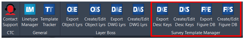
    Côté outils pour création et gestion de gabarit, nous utiliserons le panneau Survey Template Manager de la suite d’outils CIM Manager développée par CTC Software.

    Plus grande liberté à manipuler vos levés terrains

    La suite CIM Project comprend quelques outils pour manipuler votre donnée du terrain, comblant quelques manques des outils par défaut de Civil 3D. Deux d’entre eux sont d’ailleurs gratuits (restent accessibles après la fin de la version d’essai), soit Feature line to Alignment et Survey Sweeper.

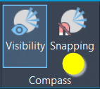
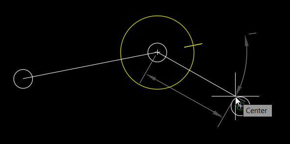
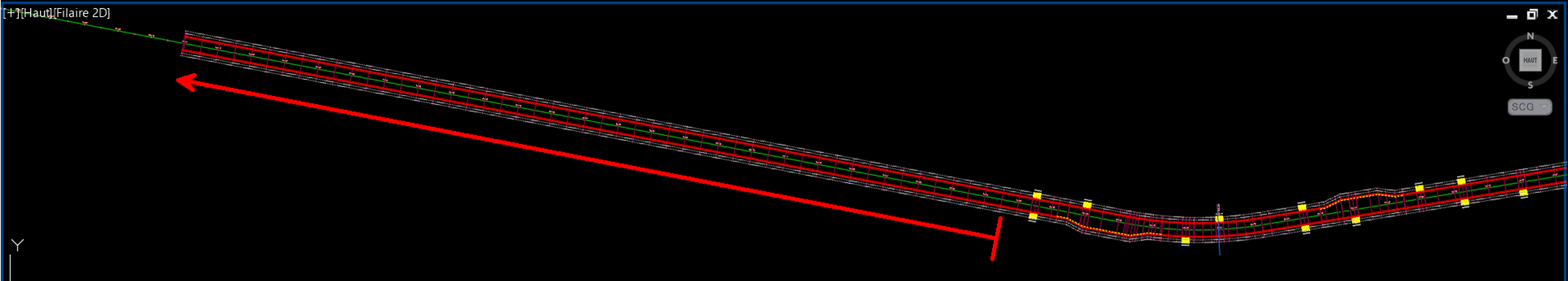
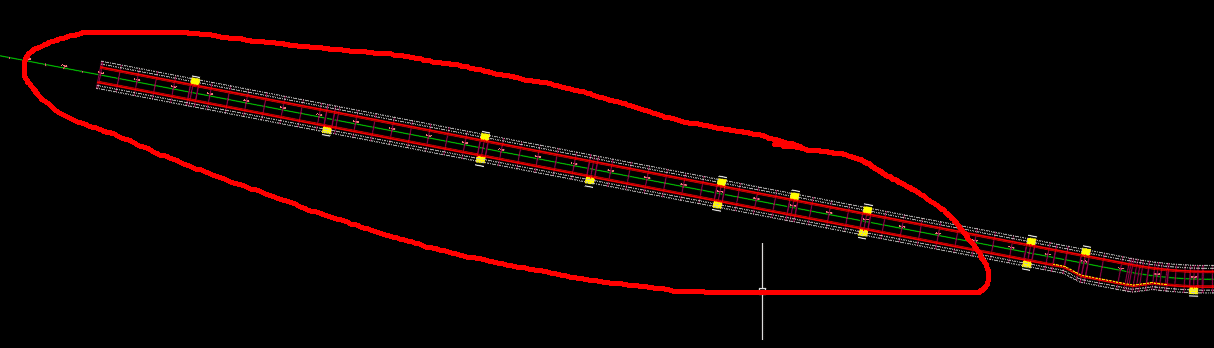
    Feature line to Alignment est un outil simple qui permet de convertir une ligne caractéristique de terrain ou une figure topographique vers un Axe avec ligne de profil en long basé sur les élévations de la ligne. Cette option de conversion peut être très pratique pour produire des vues de profil d’un levé terrain sans passer par la création de surfaces 3D, ou de convertir rapidement un centre-ligne de route levé en alignement pour produire un nouveau design.

    (Voir la vidéo explicative, en anglais)

    https://youtu.be/QYprouYjxj4

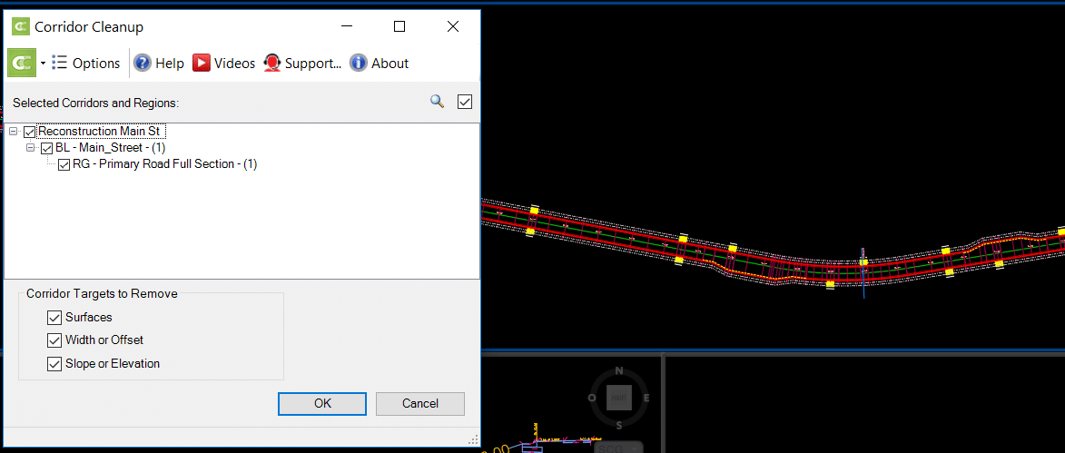
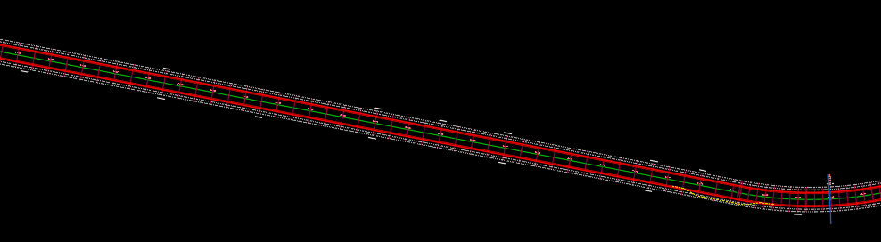
    Survey Sweeper sert activement les utilisateurs des bases de données topographiques, en donnant une option pour supprimer simultanément des points et des figures topographiques dans un dessin et dans la base de données auxquelles ils sont liés. Les correctifs sur les points topographiques et figures dans un dessin créent des doublons dans la base de données, en gardant une copie de la donnée « erronée », et sont réinsérées dans le dessin si on réimporte les données. Il est donc très pratique de nettoyer tout d’un coup, en un seul bouton.

    (Voir la vidéo explicative, en anglais)

    https://youtu.be/sbYQv4SZ-8Y

    Point file converter permet de faire une conversion des levés terrains exportés en ASCII (ex.: en format TXT, ASC, CSV, etc.) pour passer ces points d’une liste de codes de points à une autre. À partir d’une table de transition, éditable par l’utilisateur, il est possible de convertir n’importe code ponctuel ou linéaire dans un autre système. En d’autres mots, cette fonction est un outil de « recherche et remplace » hyperefficace pour passer de vos standards de levés à celui d’un client.

    (Voir la vidéo explicative, en anglais)

    https://youtu.be/QwX0f2en7xM

    Automatiser votre étiquetage de plans

    L’étiquetage fait partie intégrante du processus de mise en plan.

    En arpentage légal, on indique :

    • Les mesures de surfaces et périmètres d’un lot;
    • L’orientation et la longueur de segments limites de lots;
    • Des points cotés sur une surface;
    • Des cotes d’élévation sur des courbes de niveau.

    En arpentage de construction, on souhaite identifier :

    • Des glissières;
    • Des murs de soutènements;
    • Des points de repères ainsi que leur position par rapport au chaînage d’un axe routier.

    Peu importe votre branche de l’arpentage, l’étiquetage est un processus manuel lourd et répétitif, mais nécessaire pour produire un plan clair.

    Label Genie permet d’écourter l’application manuelle d’étiquettes en automatisant leur processus de placement.

    Par son « filtrage par calque », cette fonction peut appliquer « en masse » des étiquettes Civil 3D en utilisant les styles d’étiquettes de vos standards. Alternativement, des étiquettes personnalisées en MTEXTE d’AutoCAD pourront aussi être produits sur des objets normalement non-couverts par Civil 3D, comme les profils types et les polylignes. Toute étiquette produite par Label Genie est dynamique et annotative, comme toute étiquette de Civil 3D.

    Label Genie peut placer des étiquettes sur le dessin courant et/ou tout autre dessin au choix, étiquetant en option les références externes associées. Dans le cas d’un étiquetage sur plusieurs dessins en simultané, Label Genie tient toujours en considération le dessin courant pour les options de styles de textes et d’étiquettes, et copiera les éléments nécessaires afin de les appliquer dans les autres dessins sélectionnés.

    Sur le plan de l’application automatisée des étiquettes, l’utilisateur peut faire des combinaisons très variées d’objets « cibles » et de d’objets « sources ». Par exemple, il est possible de placer des étiquettes de surface, comme de points cotés ou de pente, à tous les vertex ou les centres de segments de toutes les polylignes sur un calque donné. Les possibilités de combinaisons sont innombrables.

    De plus, si votre dessin évolue, on peut simplement « mettre à jour » les étiquettes spécifiées pour remplacer les étiquettes obsolètes avec de nouveaux emplacements ou un nouveau contenu, en évitant un nettoyage à grande échelle.

    (Voir la vidéo explicative, en anglais)

    https://youtu.be/hSnPWiZWeSU


    Créer et mettre à jour rapidement vos gabarits d’arpentage

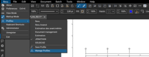
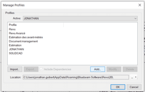
    Avec Survey Template Manager, vous pouvez gérer vos jeux d’identificateurs de description (liste liant vos codes de points à vos styles de points) et vos préfixes de figures (base de données liant vos codes de points à vos styles de lignes) dans une grille Excel.

    Ces grilles Excel incluront des listes déroulantes avec toute information nécessaire à bâtir ou modifier ces listes (styles, calques, étiquettes, etc.), dans un environnement beaucoup plus pratique que celui proposé par Civil 3D, permettant de copier/coller, modifier ET supprimer en masse les lignes des grilles. Les grilles peuvent ainsi être modifiées dans Excel et réimporter via Survey Template Manager dans Civil 3D pour créer de nouvelles listes ou mettre à jour des listes existantes.

    (Voir la vidéo explicative, en anglais)

    https://youtu.be/EPiFsaa8jaQ


    Conclusion

    Les outils pour arpenteur des CIM Project et CIM Manager nous offrent une plus grande liberté dans la manipulation et l’étiquetage de nos levés terrains, et sauvent un temps considérable aux utilisateurs en réduisant les manipulations répétitives sur l’étiquetage et la gestion de leurs gabarits. Peu importe la taille, la complexité ou l’évolution dans le temps de vos plans de levés terrains, ces outils spécialisés vous permettront d’adapter très rapidement à l’évolution de vos projets. Vos dessinateurs et chargés de projet vous en remercieront!


    Pour en savoir plus sur la suite d’outils CIM Project de CTC Software :

    https://www.ctcsoftware.com/product/cim-project-suite-2021/

    Pour en savoir plus sur la suite d’outils CIM Manager de CTC Software :

    https://www.ctcsoftware.com/product/cim-manager-suite-2021/

    Vous trouverez également, au lien suivant, nos webinaires francophones en génie civil et infrastructures :

    https://www.youtube.com/playlist?list=PLAhehuVvm9ky6D0jDNPuUd0JQelxgv3i3

    Outil Civil 3D pour simplifier vos corridors et Projets 3D – CIM Project suite 2021

    L’article de blog d’aujourd’hui présentera des outils qui accélèreront la production de vos designs de Projets 3D, qu’ils soient des corridors routiers, des intersections ou des tranchées d’excavation.

    Nous utiliserons activement les outils Corridor Cleanup, Mapper, Splitter et Merger de la suite d’outils CIM Project développée par CTC Software.

    Séparer et fusionner vos projets 3D

    Lorsqu’on planifie notre design de corridor, qu’il soit simple ou complexe, avec ou sans intersections, utilisant différents profils types en simultanés appliquées sur multiples « régions », nous sommes dans l’obligation de penser au produit final pour optimiser notre performance de travail. Souhaitons-nous :

    • Avoir toutes les rues d’un nouveau quartier afin de produire un calcul unifié des quantités de matériaux pour notre projet?
    • Séparer en différents projets 3D nos intersections, fourches et cul-de-sacs de sacs pour simplifier logiquement la création de notre design?
    • Séparer ou non notre quartier en phases de construction au sein de différents projets 3D?

    Pour un concepteur de Civil 3D, ces questions auront une importance capitale dans son design. Retourner en arrière pour fusionner ou séparer des projets 3D représente des heures de travail, à redéfinir les éléments suivants:

    • Lignes de base,
    • Régions,
    • Cibles,
    • Paramètres de fréquences,
    • Surfaces dynamiques.

    Les outils Merger et Splitter de la suite CIM Project offrent une alternative ultra performante, qui permettra en quelques clics de sous-diviser et assembler des projets 3D, peu importe l’évolution dans le temps du projet.

    Voici un projet 3D en un seul morceau couvrant tout un petit quartier qui, en cours de projet, doit être divisé en deux phases de construction :

    Voici une idée des éléments à considérer et à redéfinir dans cette séparation (et la liste peut encore être déroulée…) :
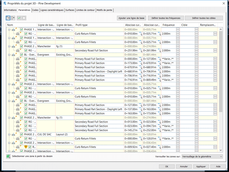
    L’outil Splitter permet de diviser en deux parties un projet 3D par ses régions ou lignes de base, tout en préservant les éléments discutés plus tôt qui servent activement à définir votre conception :

    Voici le résultat final, en quelques clics :

    L’outils Merger fait exactement le même travail à l’inverse, fusionnant deux projets 3D et plus à la fois :

    Vous pouvez optionnellement réintégrer les surfaces de corridors propres à chacun des projets dans le corridor fusionné :

    Le résultat final réassemblé parle de lui-même, gardant intacte l’ensemble des paramètres de design de chacun des projets 3D à sa source :

    L’usage des cibles dans les projets 3D : un outil simple à l’utilisation complexe

    Tout design routier utilise activement des cibles de largeur ou d’élévation pour contrôler les valeurs variables des éléments de profil type (subassemblies), que ce soit pour ouvrir progressivement une voie de virage, former un cul-de-sac, former une intersection ou créer un élargissement pour un arrêt de bus.

    Dépendamment de la complexité de vos designs (en lien direct avec le nombre de lignes de bases et de régions au même endroit), la liste de cibles possibles peut être gigantesque. Peu importe sa taille, le concepteur passera une bonne partie de son temps dans cette interface à gérer les subtilités de son design :

    CTC Software propose une alternative dans ses outils, appelée Corridor Mapper, pour sauver dramatiquement votre temps d’association de cibles, sans avoir passer par le menu précédent. Sa stratégie optimale, en fait, est d’associer des cibles situées sur des calques ayant les mêmes noms que les éléments de profils types, et ce dynamiquement (peu importe l’évolution du projet, si des cibles s’ajoutent, une simple mise à jour du lien remodélise le projet 3D).

    Dans l’exemple suivant, j’ai un corridor avec une condition de détection d’entrée de cours pour abaisser la hauteur des bordures de béton automatiquement (en rouge), ainsi que des polylignes qui créeront des élargissements de voies (en vert) :

    Corridor Mapper liera le nom de chacun de ces éléments de profils types (pouvant être personnalisés à la guise de l’utilisateur) à toutes les cibles placées sur des calques prédéfinis :

    Si les calques à spécifier ont les mêmes noms que les éléments de profils types associés, les boutons Auto-Map Layers (en rouge dans l’image précédente) permettent de les lier automatiquement.

    En quelques clics, voici le résultat :

    Et si notre projet évolue en augmentant de taille, doit-on refaire des manœuvres répétitives pour reliées nos nouvelles cibles?

    Non! Un simple clic sur le bouton Auto-map Targets passe en revu le contenu changé sur les calques des cibles pour mettre à jour le corridor :

    Pour un concepteur, on vient de se sauver facilement « une ou deux crampes au bras » par année en termes d’actions répétitives éliminées de cette façon. Voici le résultat :

    Les outils « par défaut » de Civil 3D permettent également d’associer, à un temps donné, tous les objets sur un calque comme étant des cibles potentielles, mais les différences atouts qui démarquent Corridor Mapper sont :

    • La liaison facile et efficace de cibles sur des calques spécifiques, dans une interface simplifiée sans aller-retours entre plusieurs fenêtres de paramètres;
    • L’attribution automatisée de cette liaison lorsque les calques de cibles ont les mêmes noms que les éléments de profils types;
    • La liaison dynamique d’un calque de cible et de l’élément de profil type associé.

    Additionnellement, la fonction Corridor Cleanup permet de nettoyer les cibles d’un projet 3D en partie (soit par région, ligne de base ou même type de cible) ou en entièreté, permettant de partir sur de nouvelles bases lorsqu’on reprend un design que l’on souhaite altérer ou améliorer :

    Voilà le résultat :

    Conclusion

    Le volet Corridors des outils CIM Projets nous sauvent un temps important en réduisant les manipulations répétitives sur l’édition de nos projets 3D. Peu importe la taille, la complexité ou l’évolution dans le temps de votre projet 3D, ces outils spécialisés vous permettront d’adapter très rapidement vos conceptions en génie civil. Vos concepteurs et chargés de projet vous en remercieront!


    Pour en savoir plus sur la suite d’outils CIM Projects de CTC Software :

    https://www.ctcsoftware.com/product/cim-project-suite-2021/

    Vous trouverez également, au lien suivant, nos webinaires francophones en génie civil et infrastructures :

    https://www.youtube.com/playlist?list=PLAhehuVvm9ky6D0jDNPuUd0JQelxgv3i3

    Infraworks 2021.2 Update

    Autodesk has released the next update for Civil 3D 2021.  Find the release notes here.  Here are some highlights:

    • Add decorations to component roads imported from Civil 3D.
    • Modify lane markings for component roads.  No lane marking shadow issues.
    • Various improvements to Civil Structures.
    • A new Home screen including Recent and BIM 360 tabs.
    • Select a coordinate system during model creation using the Model Builder.
    • Add a point cloud in LAS or LAZ format without first saving an RCP file.

    What Makes Digital Collaboration in Construction Possible?

    This article was originally published by Bluebeam, Inc. on the Bluebeam Blog.

    ne of the downstream effects of the 2020 COVID-19 pandemic has been a strong projected uptick in cloud software conversions. With employees increasingly working remotely, software needs to be available anytime, anywhere. Software doesn’t have to be cloud-based to be remotely accessible, but many chief information officers (CIO), even at midsize companies, have had cloud transformation on their roadmaps, and the pandemic has provided the occasion to ask: if not now, when?

    Moving key software applications to the cloud, which has already taken place across the construction industry, will have significant implications for the organisation – most obviously on the IT team that has been maintaining the software on-premises. In financial terms, the cloud-based construction management software transformation is a change from licensing software and paying annual maintenance fees to an on-demand and pay-as-you-go model. You rent the application instead of buying it.

    For end-users, a smooth cloud migration may be almost imperceptible. For instance, a user logs in to their cloud-based construction software application, works with colleagues on finalising a set of documents for a large office building project and passes them on for approval without even a hint of consideration of the technology making that series of interactions possible.

    Here are answers to common questions construction professionals may have about cloud collaboration in the construction industry and the technology behind it.

    Where’s my software?

    It’s not on your computer anymore. It’s on a remote server, being delivered to you whenever and wherever you need it. Is that something to be concerned about?

    According to Jim Prothe, marketing director at Magenium, an IT solutions consulting firm based in Glen Ellyn, Illinois, there are good reasons to be excited about the change.

    ‘A friend of mine has a business that rents an office in a Chicago suburb’, Prothe said. ‘Last summer, another tenant in their building had a fire over a weekend. All the sprinkler systems turned on, and the application server was toast. They had to spend the next two weeks rebuilding that server from month-old tape backups. So, they lost a month of data, including all their billings. If they’d been operating in a cloud environment that had an outage in a region, they’d have had built-in failover capacity; they would have been able to spin up capacity in another region, and their business would never miss a beat.’

    Where is this server?

    It’s no longer in the company’s server room – or, in cloud computing parlance, it’s no longer ‘on-premise’. Where it’s situated depends on where your business is located and what kind of cloud you’re using.

    What kind of cloud?

    There are at least three different kinds of cloud service infrastructure that drives cloud collaboration in the construction industry:

    • Public cloud: You, the end-user company, are renting services from a large vendor, perhaps even a global enterprise like Microsoft Azure, Amazon Web Services or RackSpace. Typically, your company is sharing the rented infrastructure with other companies (what the vendor calls ‘tenants’). Your applications and your data are architecturally walled off from those of other tenants, but the bits are located on shared machines. In the early days of cloud adoption, some tenants worried about the possibility of proprietary data bleeding over into other tenants’ spaces. But growing confidence in providers and in cloud technology has generally done away with that concern.
    • Private cloud: This generally refers to an infrastructure with all the characteristics of cloud architecture, but one built and maintained by your company. Large enterprises may prefer a private cloud for extremely sensitive data. It’s an exceptional situation for a mid-sized architecture, engineering or construction firm.
    • Hybrid cloud: Some organisations maintain applications in both public and private cloud infrastructures.

    As an end-user, the type of cloud probably won’t affect the availability or performance of the software.

    What are we getting from the server?

    There are at least three different levels of commitment your company could make to its cloud transformation:

    • Infrastructure as a Service (IaaS): Your company rents physical space on the provider’s servers and relies on the provider to keep them running. But that’s it – your own IT people set up and maintain all the software.
    • Platform as a Service (PaaS): In addition to the hardware, the provider maintains the operating system and all the other architectural features of the environment. Your people still maintain the applications.
    • Software as a Service (SaaS): The provider maintains everything from the operating system to the applications; your company pays to use these services on an as-needed basis.

    Where’s my data?

    Some of it is local – but the bulk of it is in the cloud. The physical location of the server generally makes little or no difference to the end-user, other than in exceptional circumstances involving regulatory compliance. Under Sarbanes-Oxley regulations, enacted after the Enron accounting scandal in the early 2000s, financial services firms often need to be able to specify to regulators where their account data is being stored. Other regulations come into play if they operate internationally. You can ensure, contractually, that your data stays within a certain region or on a certain server.

    The server’s physical location isn’t entirely irrelevant when it comes to cloud collaboration in the construction industry. The speed at which data packets travel their tortuous routes across the internet is breathtaking, but if the server is far enough away, the end-user will experience a noticeable performance lag. This is why public cloud providers – and large organisations that host their own private clouds – have multiple, redundant servers distributed among regions. The infrastructure will be designed to route your data through the nearest server and to reroute to the next-nearest server if your region’s system goes down.

    ‘Generally, the large cloud service providers give you the option to choose the region where your primary servers will be located’, Prothe said. ‘Nearly every metropolitan area will have its own dedicated servers.’

    Why are we using cloud software?

    In the short run, it’s cheaper to rent than to buy. The SaaS provider can price services inexpensively because it enjoys huge economies of scale.

    From an accounting standpoint, there are benefits in reducing capital costs and increasing operating expenditures. Cloud service contracts generally come under operating expenditures. ‘During the 2008 financial crisis, capital budgets evaporated’, Prothe said. ‘Businesses still had to operate and moving applications to the cloud was one way to keep going. In some industries, we’re seeing the same thing happen because of COVID.’

    Renting cloud software reduces the burden on a company’s IT services, because it has less infrastructure to maintain. ‘A friend of mine who runs an HVAC engineering company complains about the burden of supporting on-premises software’, Prothe said. ‘It constantly needs to be patched, and each time that introduces a new security vulnerability. The investment in IT resources to manage those changes is pretty daunting for a small engineering firm.’

    Isn’t this risky for our secret stuff?

    Some companies express concerns about their most sensitive data, but the cloud can be more secure than having your own data centres.

    A global company like Amazon Web Services or Microsoft may have thousands of full-time security people, assisted by artificial intelligence tools designed to spot or even prevent service interruptions or hacker intrusions. Their automation tools can detect unusual activity across the network, such as odd data traffic, and analyse it quickly to size it up as a potential threat. And, of course, traffic over cloud networks is encrypted end to end. The provider’s reputation is riding on the strength of that encryption.

    ‘Your instinct may tell you to maintain close control over important applications’, Prothe said. ‘But you need to ask yourself who is better at maintaining a secure infrastructure – a cloud service provider whose survival depends on their reputation for security, or your IT guys?’

    There must be a downside to cloud adoption, right?

    There is one, obvious downside: users need to have a reliable internet connection.

    Still, start-up costs are cheaper, although cloud software can cost more in the long run. ‘We have a lot of companies move applications from on-premises to the cloud, and they often need help optimising their spend’, Prothe said.’“You can spend a lot of money quickly in the cloud. You spin up a lot of power, and you pay for it on a monthly basis, so you may not notice it. You can often dial down the power you consume during off-hours when people are less likely to be online.’

    If the data structure in the cloud application is different from that of the on-premises software, the data may have to be cleaned up, restructured and normalised. Migrating data to the cloud can be expensive, cumbersome and risky if undertaken without expert help.

    Is everybody moving to cloud software?

    It depends. Some companies are using only the basic applications like email in the cloud; some are ‘cloud-first’ – the default, when introducing a new application, is to adopt the cloud version.

    It also depends on the application. Many software companies are themselves moving to a cloud-first product development roadmap, gradually transitioning their long-time customers from on-premises installations to their cloud offerings. Many new software vendors are likely to be cloud-only.

    So, the next time you log on to use any cloud-based application to review a design or communicate a set of document changes, now you know how the technology behind those transactions truly works.

    Civil 3D 2021.2 Update

    Autodesk has released the next update for Civil 3D 2021.  Find the release notes here.  Here are some highlights:

    New ArcGIS workflows:

    • Refresh data sources.
    • Import raster data as an image, or as surface data.

    New Pressure Network Workflows

    • Create parts lists from multiple materials.
    • Override pipe run offsets for specific station ranges.
    • Use expressions in profile band labels.

    Outil Civil 3D pour simplifier vos terrassements – CIM Project suite 2021

    L’article de blog d’aujourd’hui présentera des outils qui simplifieront vos designs de terrassement, en utilisant tout le potentiel des Lignes caractéristiques de terrain sans avoir à passer par les outils de Talus de Civil 3D.

    Cela dit, nous utiliserons l’outil Auto Grader de la suite d’outils CIM Project développée par CTC Software.

    Création de Talus par défaut dans Civil 3D, le pour et le contre

    Contre :

    • Tend à planter lorsqu’on projette en général des lignes caractéristiques de terrain trop lourdes en points d’intersections (souvent dû au drapage de ses élévations sur une surface trop détaillée);
    • Tend à planter lorsqu’on projette des lignes caractéristiques de terrain en talus vers des surfaces trop détaillées, nécessitant la simplification des surfaces;
    • Environnement de design peu visuel, et complexe dans son utilisation (comprenant la création de groupes de talus au préalable, la gestion de Sites rarement utilisés et l’élaboration de critères de talus dans le gabarit).
    • Petits bugs « anodins » présents depuis des années, comme la disparition des zones de remplissage lors du déplacement d’un projet/groupe de talus.
    • Travaille toujours en pentes fixes, bloquant certaines combinaisons d’entrées en terre, comme une distance fixe vers une surface (résultant potentiellement en une pente variable sur tout le terrain).

    Pour :

    • La création de transitions de pentes variables entre deux pentes fixes différentes est très efficace, le long d’une même ligne caractéristique de terrain.
    • Contient des outils de calculs de volumes et « d’optimisation » de design imbriqués au module de création de Talus.


    En résumé, si un sondage à tous les utilisateurs de Civil 3D demandait quel est l’outil de design le plus instable du produit, la grande majorité répondrait la création de Talus. Les « bonnes pratiques » dans son utilisation, comme la simplification des lignes caractéristiques de terrain et des surfaces de rattachement pour les entrées en terre, sont très efficaces pour contourner les « plantages », mais demande également de faire des compromis sur la qualité et la densité de notre donnée de base.


    Auto Grader, la solution à bien des maux de têtes en conception

    Vient à la rescousse la suite d’outils CIM Project de la compagnie CTC Software, avec son outil Auto Grader.

    Auto Grader est un outil de création de talus à part entière exploitant les lignes caractéristiques de terrain pour créer des designs de terrassement. Étant complètement indépendant des outils de création de Talus de Civil 3D, il a sa propre interface, ses propres combinaisons de critères de pentes et sa propre approche pour standardiser et reprendre des designs d’un dessin à un autre.

    L’interface d’accueil permet de gérer les Grading Families liées au dessin courant, et comprend notamment :

    • Leur création ,
    • Leur édition ,
    • Leur exportation en format .JSON, afin d’être partagés avec d’autres intervenants ou dans d’autres projets Civil 3D,
    • Un aperçu de la famille sélectionnée, en mode « vue de coupe »,
    • Des fonctions et paramètres d’ajout des Grading Families dans des surfaces Civil 3D spécifiées.

    Plan Production Workflow with CTC Tools: Sheet Sets

    Creating sheets has always been a time-consuming process and needs to be addressed quite early in the design for preliminary submissions.

    While sheet sets can help us with global information updates across sheets with the use of fields, they cannot alter or create layouts and viewports.

    Civil 3D does offer a solution for creating multiple sheets in one fell swoop. But, where these tools fall short is in flexibility and updating.

    CTC Software has come up with a set of tools to bridge this gap in flexibility and updating. This workflow can integrate seamlessly into a company standard with only the addition of 3 blocks and a few designated layers.

    Sheet Generator ties in with sheet sets for information updating, and has the power to update Plan & Profile sheets if the alignment or scope change throughout a project.

    Instead of View Frames spliced by matchlines, Plan Viewshapes inserts blocks as viewport area extents and closed polylines representing the actual shape of the viewports in layout sheets.

    Profile Views takes advantage of native tools to split up profiles for each sheet.

    Networks to Views adds all desired networks to profile views, but only assigns parts to the views they are visible in.

    Adjust & Move on Profiles allow for efficient tweaking of the profile views to best line up with Plan Viewshapes.

    Profile Viewshapes overlays the extents of the profile viewports onto the profile views for designers to make any last adjustments.

    Create Layouts takes the plan viewshapes and profile viewshapes, adds matchlines to either depending on settings, adds north arrows, and creates sheets that can be added to a new or existing sheet set.

    The true power of this tool set is the Update layouts command. As plan viewshapes change or shift this tool can write that change out to the affected layouts. It will adjust viewport shapes, north arrows, matchlines, layout names, and ripple through the sheet set.

    CTC also has great tutorials for all their tools on their Youtube Channel.

    Meridian Accelerates Time to Market through Engineering Document Accuracy

    As an excellent solution for any life sciences business with full support for E-Signatures and E-Records compliance, Accruent’s Meridian provides 3 key features:

      1. Ensure compliance with FDA 21 CFRPart 11, and Annex 11
      2. Fully realized change control for all engineering documentation
      3. Enable team collaboration through a secure single source of truth

    Here are some big numbers that prove Meridian is one of the top document management platform choices:

    Stats related to Meridian's user base

    Accruent’s Meridian technical document management solution can assist life sciences companies overcome the common issues found when dealing with vast amounts of asset information while maintaining full compliance requirements required by the industry. Teams will always have access to the latest versions of documents that are fully approved.  Through electronic signature control, your business will accelerate time to market by managing change control faster and with full traceability for audits.

    What can your company achieve with Meridian?

    Always be in control of your technical data.

    • Ensure the team is working on the latest approved documentation.
    • Provide accurate printing of documents with watermarking ability.
    • Full version control and revision management in a secure environment.

    Deliver new products on time.

    • Arm your maintenance teams with the most up to date documentation in the field.
    • Provide a robust and easy search tool for all technical documents.
    • Avoid production delays due to out of date information.

    Reduce audit issues with less risk of noncompliance.

    • Full audit trails – know when and who made changes.
    • Avoid costly fines and delays with life science specific regulations.
    • Workflows ensure consistency across teams and working sites.

    Empower your teams with improved communication.

    • Access to markup tools and comments on all technical documents.
    • Find the exact document you need quickly via robust search features.
    • Improve team cohesion by providing the same view of official documentation to both engineers and maintenance & operations.

    To learn more about Meridian solutions and how they can help your team, please contact the SolidCAD Meridian team.

    Bluebeam: PROFILES

    What is a profile?

    One of the most essential features in Bluebeam that will help all users to organize themself is maybe one of the less known; Profiles.

    Profiles in Bluebeam are important. It is not just about having a custom interface. It’s more about having an organized tool that will make you more efficient to work and you will be able to deploy at large in your department. In addition to the interface, by exporting a profile, you export everything you customized in Bluebeam (including Tool Sets and Markup list columns). So everybody is unified in their work.


    How to create a profile

    When you start Bluebeam, you will first go to the Revu menu and click to see the menu show up. Then go to Profiles and select Manage profiles:

    A dialog box will open, and you will be able to add a new profile:

    Click on Add… and another window will open (don’t worry there is no more after that)

    Add your name or your service/department name and click OK. Your screen will flash (don’t worry it is not exploding) and now you are in your profile.

    You will notice it looks like the previous one you were in. That’s normal. Revu doesn’t want you to create everything from scratch so it uses the last profile as a canvas you will work on.

    But the first step is done. Let’s customize it:

    How to custom my interface?

    Before customizing your profile, you will need to ask yourself what you need to do with Bluebeam. This little brainstorm will be valuable to know what we will show and we will hide.

    From there you have 3 ways to do it.

    The first will simply consist of right-clicking where the current icons are to bring up the toolbar’s menu.

    Then select from the available menu the toolbars you think you need. When you have done this, the selected bar will be displayed in your interface.

    Now we will see how to create your own toolbar.

    To do this, right-click at the top of the screen to bring up the toolbar menu and select Customize

    A dialog box will open to allow you to customize existing toolbars and create your own toolbar

    In order to facilitate the understanding of this part, we will identify each part and detail them:

    1- Toolbars

    These are all the toolbars that currently exist in Bluebeam and this is also where you will be able to create your own

    2- Items

    These are the tools which are the toolbars that we select in part 1.

    3 – Orders (and Categories)

    This is where all the tools Bluebeam offers are located. These are classified by category

    To create your own personalized toolbar, click on the   icon and a window will show up

    Name your toolbar as you wish and click OK

    After that, we are going to select the tools that we are going to need for our most common tasks and add them to our custom bar.

    The tools that we will put must be the ones we want to have at hand because they are the ones we will use most often

    Finally, let’s see the 3rd and final way to add tools to your custom bar.

    When you navigate the Bluebeam menus to choose a tool, you will notice a pushpin next to the name of the tool. Click on it to bring up the menu of toolbars.

    Select where you want to add this tool (in which bar) and now the tool is available on your toolbar.

    Remember to save everything by going in Revu →Profiles→ Save Profiles before closing Bluebeam.

    Export a profile

    To export a profile and everything in it, go to Revu → Profiles → Manage profiles.

    Select the profiles to export and click on Export. Choose the location where your profile will be exported. Copy/paste it into an email and send it to everyone who will work with it from now on.

    Civil 3D Pressure Pipes

    Civil 3D 2021.1 introduced several new features including a new compass when creating a pipe run.  This is excellent news, but depending on your modeling requirements, it can cause an issue if you leave in a new setting.

    In the examples below, the parts list has no bends, and they are not needed for this design.  The pipe runs as required to be drawn like a polyline.  While working with a customer, I ran into this issue, but I could not find the solution, and surprisingly, neither could Autodesk.  Thanks to my esteemed colleague, Colin Gaudet for discovering what turns out to be a very simple solution.

    2021.0

    This is the behavior from 2021.0 and it is the expected behavior.


    2021.1

    This is the behavior after installing 2021.1.  The compass indicates that there are no bends and it will not allow any angle to be drawn, only a straight line.


    The Setting

    There is a new setting to allow pipe runs to be “snapped” to known bend angles.  Turn off the new setting to return to the expected behavior when there are no bends.  The compass remains, but it now allows any angle to be drawn.