• Civil 3D Double Click Customization

    Is there a Civil 3D object that you would like to double click and run a specific command?  if so, read on.  (This works for AutoCAD commands too.)

    Try double-clicking an Alignment.  The AutoCAD properties palette appears.  What if we want the Alignment Properties dialog instead?  Or if you want the Feature Line Quick Elevation Edit tool to be run when you double click a Feature Line.

    Edits to the CUI file are required.  Please do yourself a favor and create a partial CUI file and make these edits in there.  And while you’re at it, save this file somewhere like My Documents.

    1.  Determine the object name.  Run the LIST command and select the object.  The object name will be shown.  Mine is AECC_ALIGNMENT.
    2. Run the CUI command.  The double-click assignments are stored in the CUI file.
    3. Right-click to add a new double-click action.  Name it something like Alignment Properties

    5. On the right half of the CUI editor, enter the appropriate object name.

    6. Find the appropriate command in the bottom-left window.  In this case, Alignment Properties.  Drag it onto your new double-click action.

    7. Close the CUI editor.

    8. You’re done!  Double click the object and the command will be run.

    Tip: 5 steps to great renders from Lumion

    This article was originally published on the Lumion Blog.

    You’ve finished your 3D model and imported it into Lumion. Now, it’s time to make it look great. With all of Lumion’s functionality just inviting you to transform your 3D model into a beautiful render, it can be difficult to know where to start. This blog gives you step-by-step hints of what you can do.


    Villa, rendered in Lumion 9.5 by Gui Felix.


    As intuitive and dependable 3D rendering software, Lumion makes it easy to quickly breathe life into your designs.

    Simply imagine how you want to show your design, and you’ll find a wide range of easy-to-apply tools, features and effects. But before you start building a scene and rendering, there are a few questions you should answer first — 1) how do you want to artistically communicate your model and designs, and 2) how can you make it happen in Lumion?

    Building an artistically compelling image or animation of your designs requires a vision of what you want to achieve. To enhance that vision in your mind, some questions to ask yourself may include:

    1. What emotions do you want to convey?
    2. Are you going for light and colorful, grey and bleak, or something else?
    3. Should the images look realistic or sketchy?
    4. Which parts of the building are you trying to emphasize?

    To help streamline the development of your renders, we’ve provided 5 tried-and-true tips for transforming blank 3D models into beautiful, compelling images and videos.

    Step 1: Find the best point (or points) of view in your scene


    • Use at least one composition rule when framing and finding a camera angle for your image renders. Just a few of these rules include ‘simplify the scene,’ ‘use leading lines,’ ‘be creative with colors,’ and so on.
    • When making an animation, set the camera height to the human eye level. The camera angle shouldn’t be too wide so as to avoid perspective distortion.

    Interior wave lounge, rendered in Lumion 9 by ‎Kamon Tangruen.

    Step 2: Set up the scene’s lighting


    • Find the best position for the sun so that it draws attention to the parts of the building that you want to highlight. You can use the “Sun Study” effect to accurately simulate the sun location at a particular location, time and date. Other effects such as the “Sun” effect and the “Real Skies” can help you control the environmental lighting in your design.
    • Add interior and mood lighting. Even if the scene you want to show takes place during the daytime, interior and mood lighting can subtly communicate that the building is being used. You can also use volumetric lighting for an extra atmospheric feeling.
    • Balance the shadow brightness and coloring with the context surrounding the building. For example, outdoor shadows tend to show with a bluer color.
    • Avoid a high level of contrast in non-important areas. This is because high-contrast areas can sometimes direct attention to the wrong points in your design.

    Villa in UAE, rendered in Lumion 9 by CRIO Design Studio in collaboration with Arch. Alaa Hossari.

    Step 3: Make materials look beautiful with texture and age


    • When rendering, enable “Speedray reflections” and put reflection planes on big, flat surfaces.
    • Tweak the glossiness slider of the floor and ceiling materials. In many cases, making your materials a little more reflective will work better than static, non-reflective surfaces.
    • Do not use simple digital colors, include plain green, red, blue, purple, yellow. These simple digital colors can look ugly when applied to materials. Consider using a more natural (and more realistic) color palette for the entire scene.
    • Sometimes it is better to replace diffuse textures with plain colors (using the top slider in the material editor) and use bumps but without maximal intensity.
    • Consider showing a little age and weathering with the “Weathering” slider, located in Lumion’s material editor.

    GIF showing various wall materials, many of which were included in the Lumion 9.5 update.

    Step 4: Adding effects

    • Use the “Color Correction” effect (especially the first slider — Temperature) as it adjusts the color tone of the image and adds dark shadows where necessary.
    • Add a little bit of “Chromatic Aberration” and a very tiny value of the “Fish Eye” effect for a small, optical imperfection.
    • Add “Sky Light” and “Hyperlight” for still images and videos. For the most impact with Sky Light, turn the Sky Light render quality to ultra (which also means “ultra-slow render speeds”).
    • Use the “Sharpness” effect and set the slider to a low value to make the picture look a bit more ‘flat,’ as if were printed on a piece of paper.
    • “Depth-of-Field” (DOF) is really useful for narrow camera angles. Generally, you shouldn’t use this effect if you have wide camera angles.
    • Always add reflections to water and glass planes.

    Step 5: Extra details – every single shot needs them!

    • Furniture is very important for interiors and exteriors. Select and add furniture models from the Lumion object library and fill out some empty spaces. The idea is to make the spaces look “lived-in,” where you show how people might use a building, home, public space, etc.
    • Cars are really effective models when forming the “border areas” of a still render or a movie frame. Try to avoid having cars in the center of your composition.
    • By including people models in your render, you can easily show your audience how you’ve envisioned the relationship between people and a building design. Nevertheless, make sure that your people don’t dominate the render. Their faces should not be too visible so that you don’t distract viewers from the model design. Using silhouettes from the library is a good way to achieve this neutrality with the scene’s people models.
    • You can effectively create picture borders and backgrounds with trees and plants from the content library.
    • Remember that the background of your scene has a huge impact on the look of your building design. Even if the background is blurry, having the feeling of a real city or forest in the background can enhance the realism of the scene while making the entire render easier for the viewer to understand and digest.
    • While the “Real Skies” are beautiful and realistic, they can distract the viewer from the building in some cases. If you feel that the skies are distracting, you have a couple options. For one, you can use one of the “clear” Real Skies or you can add the Sky and Clouds effect and turn up the “cloud softness” slider to blur the clouds. Another option is to turn off any cloud effect and adjust the “clouds” slider in Lumion’s Build Mode to create a distraction-free, clear sky. Below, you can find a picture showing the difference between “no clouds” in Lumion and the clear Real Skies.

    CTC & Feature Lines – Establishing the Hierarchy of Power!

    Which option do you choose when creating a feature line? In my early days of learning Civil 3D I was given an analogy of buckets. That any of the objects in a site, “Bucket”, could not interact with other objects, this was the purpose of sites.

    This analogy was half-true and only the tip of the iceberg.

    For starters, sites can only house certain objects, and only parcels and grading groups are confined within sites.

    Alignments and feature lines have the option.

    The limited interaction between these “Buckets” only limits the interaction of the objects in a site from communicating with the objects in another site. That’s why we can choose to restrict feature lines and alignments.

    However, when feature lines are contained in a site, we have additional control over their interactions with one another.

    This is called Split Point Resolution and it allows us to set which feature lines govern at a crossing. Assigning styles to feature lines, we can set which styles are the most important for the design.

    I use this for lot grading to manage a variety of constraints and to make sure that right of way and existing elevations are respected.

    Using the split point resolution while grading this cul-de-sac, it ensures the lot lines obey the right of way and the existing tie in points.

    This technique can be used in many other grading scenarios like drops in a curb or pond access paths.

    It is a powerful concept that not many designers have embraced yet.


    And if that isn’t powerful enough for you, consider using CTC Software’s Auto Grader to automate the rest of your grading! This tool dovetails beautifully with the native split point resolution for feature lines in sites.

    Auto Grader has 3 different types of “Grading Families” that can be used to tackle almost any grading project.

    Parallel Grading allows mass dynamic stepped offsets from one or multiple baseline feature lines. Offering flexible grading for project areas such as curbs or ponds

    Perpendicular Grading allows mass insertion of elevation points/grade breaks across feature lines connecting to a baseline feature line. Offering automated grading solutions for lots in a subdivision or drop curbs.

    Template Grading is the newest addition to this tool allowing incredibly flexible 3D insertion control over template feature lines. Allowing you to establish grades from baseline feature lines and associate relative grades to the inserted template. This offers unparalleled flexibility for operations such as building envelope insertion.

    Hopefully, this challenges you to find even more efficiencies in your use of feature lines.

    11 Revu Tools to Ease the Punch Walk Process

    This article was originally published by Troy DeGroot and Bluebeam, Inc. on the Bluebeam Blog.

    Today I want to talk about Punch Walks, QA/QC, or whatever you might call it when you collect field data during or after construction.

    I started my career detailing structural steel. As a result, I was often required to juggle large plan rolls, tape measures, pens, and a level to measure existing conditions.

    These measurements would then be brought back to the office to make sure the railings and stairs fit perfectly when fabricated. Obviously, this was before emerging technologies like building information modeling (BIM) and laser scanning.

    So, how has Bluebeam Revu improved field data documentation?

    Here are 11 of my favorite Revu tools that ease field data collection and distribution.

    Standardizing plan symbology will replace long, written notes—increasing consistency, legibility and speed. These symbols are manually created ahead of time or on the fly. To save the most time, I suggest building your symbol list in Microsoft Excel. Importing the CSV file automatically generates large lists of symbols, along with the associated comment.

    Embed images, 360-degree images, or even videos with audio giving a clear description of the field conditions. The Flipbook is a clean way to add many images directly where they apply on the plan rather than off to the side someplace with a reference number.

    Create a template PDF form to quickly fill in the information needed. Before I save the template, I like to add a blank page after the form. This provides a place to drop a related image or Snapshot from a plan or detail, including clouds and other markups. Save this to your template folder for quick access every time.

    Speaking of the Snapshot, quickly grab a screenshot of the affected area of the drawing, saving it directly to the Clipboard. Paste this image on your RFI form, in a written report, or directly into an email. Your markups will come over, assuring the form matches exactly what’s on the large plan.

    Use Studio Projects to keep data organized and available to all stakeholders. A Digital Dashboard is a great way to organize everything in a visual format, similar to a website.

    Before each site walk, create a layer naming it with the date, then set it to Current. This will record all the markups on an isolated layer. Turning layers on and off allows you to track inspection progress.

    Create Spaces to track where on the plan your markups are located. If you walk into a room on-site and want to know all the information associated with that room, simply sort your markups List by Spaces.

    Create custom Columns to track individuals or maybe subcontractors who are “Responsible” for changes or fixes.

    Create custom Statuses to track progress on your projects, whether you use them to mark things complete for yourself internally or the general contractor who owns the documents. Changing a Status will automatically stamp the time, date and author. These status updates cannot be edited or removed by anyone.

    A custom Legend is a great way to represent the Markups List visually directly on the sheet. This could include a description of the symbol or even the number of times it was placed.

    Finally, Summary Reports are extremely powerful using Bluebeam Revu. Creating a PDF Summary report of all the markups on the drawing can be a clean and easy way to transfer information to others on the team. This is especially true when including a Capture Media Summary, which will embed all the images into the document.

    You may be using some of these tips already. I hope you learned a few more to streamline and improve the quality of your Punch Walks, QA/QC or whatever you might call it when you collect field data during or after construction.

    If you like these tips and want to see the technical steps, check out my YouTube playlist from last summer.

    Flexible, Customized Legends and QTOs with CTC’s Data Wizard.

    Flexible, Customized Legends and QTOs with CTC’s Data Wizard.


    How do you tackle quantity takeoffs in your projects? Do you use Civil 3D’s QTO Manager? Do you scale on paper or PDF’s?

    Between the inaccuracy of paper and PDF calculations, and the tedious setup and inflexibility of the MTO Manager, we don’t have a great solution for quantities of what’s in our projects.

    Data Wizard can make this cumbersome task a lot more efficient and accurate. This tool searches your drawing for Civil 3D & ACAD point, line, and area type objects then tabulates them all for you.


    This is a very versatile tool, and once objects are selected and filtered, we can choose specific data to extract. In the case of QTO, a layer description can be used to label the item. Then areas, lengths, and counts can be tabulated for each respective item.


    We can then sort and prep this data for AutoCAD Table insertion, or export to Excel. Data Wizard allows you to customize what you are looking for every step of the way!


    Once the QTO is set up, we can also save the setup to a template to share among projects. This speeds up the QTO process even more for future projects.


    This is just one way to use Data Wizard. Alternatively, we can extract graphics and layer descriptions to produce sheet-specific legends for our plan production.


    This tool will save time and reduce human error with any tabulation tasks across your projects!

    Automated, Flexible, and Iterative Plan Production Tools. CTC’s Sheet Generator Workflow is the Whole Package.

    You can’t afford to create plan and profile sheets without these tools!

    If you have ever tried to create Plan & Profile sheets on mass with the Native View Frame tools it sure beats doing it by hand. But it also still requires a lot of manual manipulation after the layouts are created. And worst of all, you have to get it right the first time because the tools were not built to offer an iterative workflow.

    CIM Project Suite’s Sheet Generator workflow is a set of tools to speed up and increase the flexibility of the sheet creation process.

    Native View Frames vs. CTC Software’s Plan Viewshapes

    Plan Viewshapes consist of a block to represent the extent of your allowable viewport area in a sheet and a polygon to represent the actual shape and positioning of the viewport you would like to create. No more chopping View Frames at matchlines and hatching the rest of the rectangular area in your sheets.

    Creating profile views natively vs. with CTC’s CIM Project Suite.

    This is a bit of a trick comparison because the Sheet Generator workflow takes advantage of the native tools for creating profile views. Although, Sheet Generator offers much more mass editing controls for profile view heights, stationing, and object projection. These tools give you the ability to have uniformity across any number of profile views, and have lots of flexible options for centering these profile views on key information.

    The sheets that are created from CTC’s workflow will pull from company templates for sheet layout, and integrate into Sheet Sets seamlessly. The previously specified Plan Viewshapes and Profile Viewshapes create polygonal viewports with custom matchline blocks. The layout creation also adds north arrows, names layouts, and adds sheets to sheet sets automatically.

    The most important part of this workflow is that if the linear design changes in any way, all the sheets can be updated. Not recreated but updated! This means that custom notes and legends, details and blowups will all stay in the layouts. Updates to viewports, north arrows, stationing, matchlines, layout names, and sheet set information all take place automatically when the layouts need to incorporate a design change. This iterative flexibility is a game changer for large projects, it eliminating human error, and executing massive changes to sheets with just a few clicks.

    I hope the Sheet Generator workflow peaks your interest and helps you to find a new level of intuitive automation for your projects.

    CTC also has great tutorials for all their tools on their Youtube Channel.

    https://www.youtube.com/watch?v=_IlLnoK1qrk&list=PLTCH_HgPsbw_DWqEaVLF9xhWMjGPey9SI

    Create Your Own AutoCAD Tutorial Library

    Are you or do you have a staff member in your office who likes to create tutorial content?  Or maybe you simply have some web links to which you’d like to regularly refer.  Maybe you’d like to share these tutorials with the rest of your AutoCAD team.  Sure you can tell them where the videos, documents, or web links are, but the users must open them outside of the AutoCAD environment.

    What if the users could access this content right within AutoCAD?  The closer the help is to the user, the better, I always say.  Consider creating a custom tool palette containing buttons to open these tutorials, and sharing it with the users.

    I’ll go on the assumption you already know how to create and share a tool palette.  I’ll show you how to create tools that link to files or web links.

    Create the Tool

    Drag a line or a text object to your new tool palette then edit its properties.

    Web Link

    Edit 5 properties:

    • Name.
    • Description.
    • Specify Image.
    • Turn off the flyout option
    • Edit the Command String.  Enter this information ^C^C_browser https://WebLink  Paste the link after browser.

    File

    The only difference between this tool and the web link is the Command string which uses a little LISP code.  Enter the path to your file after findfile, within the quotes.  DO NOT use back slashes, only forward slashes.

    • ^C^C (startapp “explorer.exe” (findfile “C:/temp/1.docx”))

    That’s it.  Make it easy for your users to get the help they need!


    A Document Management Workflow for the Modern Construction Project

    This story was originally published by Bluebeam, Inc. on Built, the Bluebeam Blog.

    Most construction projects are massive undertakings. Teams of architects and engineers work tirelessly preparing large volumes of design documents before they ultimately make their way onto a construction jobsite, where workers labor vigorously to build off those plans down to the tiniest details.

    The evolution of technology in the construction industry has made the arduous task of managing the flow of such large project document loads easier. Once initial plans are made, multiple rounds of revisions must take place among varying project stakeholders before they’re ultimately pushed out to the field, where more revisions may occur as new challenges emerge.

    Pablo Giraldo, an assistant construction technology manager with The Walsh Group in Atlanta, Georgia, is one among a crowd of passionate and tech-savvy construction professionals who have embraced digital transformation in the industry. Giraldo has spent a lot of time, including through his own growing YouTube channel, figuring out how to make digital transformation of document management work on his projects.

    Here is a breakdown of how Giraldo leads document management using the varying tools within Bluebeam Revu, based on his recent presentation as part of Bluebeam’s ongoing virtual events series.

    Create Sets

    The first thing Giraldo does to initiate his document management workflow is to create document Sets in Revu.

    Sets allow Revu users to open a collection of plan documents as if they were a single file. Pages in a Set are organized in a specific and sorted order, including any revisions. Sets ultimately allow users to navigate through multiple files in Revu as if they were one document.

    Publishing the latest Set ultimately allows files to load faster for workers in the field; it also allows a check-out/check-in system that allows users to check-in/out a document one person at a time.

    https://youtu.be/XOmzLYnW3gk 

    Batch Link

    Next, Giraldo Batch Links his Set. Batch Link in Revu automatically creates navigational hyperlinks within a particular group of documents based on user-defined criteria. Batch Link, which is only available in the eXtreme edition of Revu, can be run against multiple PDFs or a single, multi-paged PDF.

    “This is beneficial as you’re going through the drawings to easily flip back and forth through different documents,” Giraldo said.

    This is particularly helpful for workers in the field, Giraldo said, as they can transition between different documents on their iPads, looking at different sections of drawings as they spot important details while working on the jobsite.

    Hyperlink drawings

    In addition to Batch Linking document Sets, Giraldo often uses hyperlinks throughout different documents in other ways to help provide field workers and other collaborators with easy ways to find and reference critical project information as they work.

    Links, which can be placed on anything in a PDF, including markups, can include anything from linking to other project documents to reference websites to any other important, web-accessible information.

    https://youtu.be/gjRN4JM03ms 

    Publish

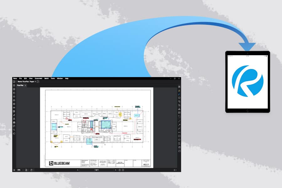
    Once Giraldo has set up all his Sets, Batched Linked and set up hyperlinks to other documents or resources throughout the documents, now it’s time to publish the Sets and send them out to workers in the field. There, workers will use the Bluebeam app on iPads to sync to the latest document Sets to reference and work off while in the field.

    Anytime a worker in the field can connect to the internet, either via WiFi or cellular connectivity, they can hit “Sync” in the Bluebeam app. Then all the documents will automatically download the latest set of drawings, Giraldo said.

    Create dashboard

    One of the powerful ways to help everyone collaborating on documents—whether they’re in-office engineers approving plans or field workers implementing them—is to create a digital project dashboard in Revu. Digital dashboards are hyperlinked, button-enabled PDFs that can be configured and designed such that users have a simple place for reference for all project documents and resources, alleviating the need for anyone to have to navigate through complex folder structures to find documents.

    Giraldo said once he’s completed the above steps, he ultimately creates two project dashboards: one for workers who interact with documents in the office, and another for workers in the field. The dashboard for workers in the office is slightly more robust, with multiple buttons directing workers to key documents and resources. The dashboard for field workers is less detailed, allowing them a simple and easy-to-understand interface as they need to review documents while working on hectic jobsites.

    https://youtu.be/knTzovEw5Fs?list=PLJ7Sea2rdFrlbonLl3F3u3-w35nkIXLdh

    Create Studio groups

    Studio, which provides users with document management and real-time collaboration capabilities, is another tool Giraldo uses on his projects. Creating groups within Studio allows the administrator—in this case Giraldo—the ability to provide different users access to different documents within the Studio Project as well as the ability to collaborate on document review in Studio Sessions.

    Users can have three levels of permissions within Studio: read, read/write and read/write/delete. “This can function as your server,” Giraldo said of Studio Projects, although most larger firms ultimately store their files elsewhere. “I’ve seen small companies rely on Studio Projects entirely for their document management.”

    Bluebeam for iPad

    A major asset for Giraldo’s document management implementation with his projects has been use of iPad in the field. The Revu for iPad app, in addition to giving field workers access to view project documents nearly like an in-office worker would on a desktop computer, is especially great when it comes to project tracking, Giraldo said.

    Moreover, Giraldo has used tablets in the field to take pictures of completed work to store in the document, such that workers can view project elements as they’re installed within the drawings as construction progresses. Giraldo has also taken to dictating notes using the audio recording capability within the iPad app to make notes on certain markups within drawings while out in the field.

    Track work with statuses

    Lastly, the Markups List in Revu includes a Status column that allows Giraldo and other users the ability to track the progress of different project elements. What’s more, the status column is followed by a color column that allows users to color-code different statuses.

    Giraldo on a recent project, for instance, had three different statuses displaying what stage a series of pre-cast panels were at: ordered, delivered, installed. To set a status, users can right click on a markup, click “Set a Status,” then pick the project element. This can be done both in the field on a tablet and in an office on a desktop.

    Streamlined efficiency

    Overall, this digital document management workflow has helped Giraldo and the rest of his project team cut down on printing and use of paper documents, which often led to confusion and disorganization on jobsites. It has also helped field workers be more efficient, Giraldo said, as they no longer must account for and reference rolls of paper documents.

    Thanks to these tools provided by Revu, as well as construction professionals like Giraldo who are willing to figure out the connective elements of establishing a fully functional digital document workflow, construction workers have an example of how to store, organize, track and find important project documents and resources digitally, making the office-to-field document flow easier to manage.
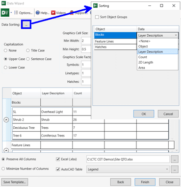
    Outil Civil 3D pour arpenteurs – Suite de projets CIM 2021

    L’article de blog d’aujourd’hui présentera des outils spécialisés à l’arpentage, accélérant d’une part la production de vos plans dans Civil 3D et d’une autre part l’élaboration de vos gabarits. Nos objectifs :

    • Vous offrir une plus grande liberté dans la manipulation de vos levés terrains.
    • Transformer des heures en étiquetage de plans à quelques minutes par automatisation.
    • Créer et mettre à jour rapidement vos gabarits d’arpentage à l’aide d’éditeurs tabulaires.

    Côté outils de production, nous utiliserons Feature line to Alignment, Survey Sweeper, Point File Converter et Label Genie de la suite d’outils CIM Project développée par CTC Software.

    Côté outils pour création et gestion de gabarit, nous utiliserons le panneau Survey Template Manager de la suite d’outils CIM Manager développée par CTC Software.

    Plus grande liberté à manipuler vos levés terrains

    La suite CIM Project comprend quelques outils pour manipuler votre donnée du terrain, comblant quelques manques des outils par défaut de Civil 3D. Deux d’entre eux sont d’ailleurs gratuits (restent accessibles après la fin de la version d’essai), soit Feature line to Alignment et Survey Sweeper.

    Feature line to Alignment est un outil simple qui permet de convertir une ligne caractéristique de terrain ou une figure topographique vers un Axe avec ligne de profil en long basé sur les élévations de la ligne. Cette option de conversion peut être très pratique pour produire des vues de profil d’un levé terrain sans passer par la création de surfaces 3D, ou de convertir rapidement un centre-ligne de route levé en alignement pour produire un nouveau design.

    (Voir la vidéo explicative, en anglais)

    https://youtu.be/QYprouYjxj4

    Survey Sweeper sert activement les utilisateurs des bases de données topographiques, en donnant une option pour supprimer simultanément des points et des figures topographiques dans un dessin et dans la base de données auxquelles ils sont liés. Les correctifs sur les points topographiques et figures dans un dessin créent des doublons dans la base de données, en gardant une copie de la donnée « erronée », et sont réinsérées dans le dessin si on réimporte les données. Il est donc très pratique de nettoyer tout d’un coup, en un seul bouton.

    (Voir la vidéo explicative, en anglais)

    https://youtu.be/sbYQv4SZ-8Y

    Point file converter permet de faire une conversion des levés terrains exportés en ASCII (ex.: en format TXT, ASC, CSV, etc.) pour passer ces points d’une liste de codes de points à une autre. À partir d’une table de transition, éditable par l’utilisateur, il est possible de convertir n’importe code ponctuel ou linéaire dans un autre système. En d’autres mots, cette fonction est un outil de « recherche et remplace » hyperefficace pour passer de vos standards de levés à celui d’un client.

    (Voir la vidéo explicative, en anglais)

    https://youtu.be/QwX0f2en7xM

    Automatiser votre étiquetage de plans

    L’étiquetage fait partie intégrante du processus de mise en plan.

    En arpentage légal, on indique :

    • Les mesures de surfaces et périmètres d’un lot;
    • L’orientation et la longueur de segments limites de lots;
    • Des points cotés sur une surface;
    • Des cotes d’élévation sur des courbes de niveau.

    En arpentage de construction, on souhaite identifier :

    • Des glissières;
    • Des murs de soutènements;
    • Des points de repères ainsi que leur position par rapport au chaînage d’un axe routier.

    Peu importe votre branche de l’arpentage, l’étiquetage est un processus manuel lourd et répétitif, mais nécessaire pour produire un plan clair.

    Label Genie permet d’écourter l’application manuelle d’étiquettes en automatisant leur processus de placement.

    Par son « filtrage par calque », cette fonction peut appliquer « en masse » des étiquettes Civil 3D en utilisant les styles d’étiquettes de vos standards. Alternativement, des étiquettes personnalisées en MTEXTE d’AutoCAD pourront aussi être produits sur des objets normalement non-couverts par Civil 3D, comme les profils types et les polylignes. Toute étiquette produite par Label Genie est dynamique et annotative, comme toute étiquette de Civil 3D.

    Label Genie peut placer des étiquettes sur le dessin courant et/ou tout autre dessin au choix, étiquetant en option les références externes associées. Dans le cas d’un étiquetage sur plusieurs dessins en simultané, Label Genie tient toujours en considération le dessin courant pour les options de styles de textes et d’étiquettes, et copiera les éléments nécessaires afin de les appliquer dans les autres dessins sélectionnés.

    Sur le plan de l’application automatisée des étiquettes, l’utilisateur peut faire des combinaisons très variées d’objets « cibles » et de d’objets « sources ». Par exemple, il est possible de placer des étiquettes de surface, comme de points cotés ou de pente, à tous les vertex ou les centres de segments de toutes les polylignes sur un calque donné. Les possibilités de combinaisons sont innombrables.

    De plus, si votre dessin évolue, on peut simplement « mettre à jour » les étiquettes spécifiées pour remplacer les étiquettes obsolètes avec de nouveaux emplacements ou un nouveau contenu, en évitant un nettoyage à grande échelle.

    (Voir la vidéo explicative, en anglais)

    https://youtu.be/hSnPWiZWeSU


    Créer et mettre à jour rapidement vos gabarits d’arpentage

    Avec Survey Template Manager, vous pouvez gérer vos jeux d’identificateurs de description (liste liant vos codes de points à vos styles de points) et vos préfixes de figures (base de données liant vos codes de points à vos styles de lignes) dans une grille Excel.

    Ces grilles Excel incluront des listes déroulantes avec toute information nécessaire à bâtir ou modifier ces listes (styles, calques, étiquettes, etc.), dans un environnement beaucoup plus pratique que celui proposé par Civil 3D, permettant de copier/coller, modifier ET supprimer en masse les lignes des grilles. Les grilles peuvent ainsi être modifiées dans Excel et réimporter via Survey Template Manager dans Civil 3D pour créer de nouvelles listes ou mettre à jour des listes existantes.

    (Voir la vidéo explicative, en anglais)

    https://youtu.be/EPiFsaa8jaQ


    Conclusion

    Les outils pour arpenteur des CIM Project et CIM Manager nous offrent une plus grande liberté dans la manipulation et l’étiquetage de nos levés terrains, et sauvent un temps considérable aux utilisateurs en réduisant les manipulations répétitives sur l’étiquetage et la gestion de leurs gabarits. Peu importe la taille, la complexité ou l’évolution dans le temps de vos plans de levés terrains, ces outils spécialisés vous permettront d’adapter très rapidement à l’évolution de vos projets. Vos dessinateurs et chargés de projet vous en remercieront!


    Pour en savoir plus sur la suite d’outils CIM Project de CTC Software :

    https://www.ctcsoftware.com/product/cim-project-suite-2021/

    Pour en savoir plus sur la suite d’outils CIM Manager de CTC Software :

    https://www.ctcsoftware.com/product/cim-manager-suite-2021/

    Vous trouverez également, au lien suivant, nos webinaires francophones en génie civil et infrastructures :

    https://www.youtube.com/playlist?list=PLAhehuVvm9ky6D0jDNPuUd0JQelxgv3i3

    Outil Civil 3D pour simplifier vos corridors et Projets 3D – CIM Project suite 2021

    L’article de blog d’aujourd’hui présentera des outils qui accélèreront la production de vos designs de Projets 3D, qu’ils soient des corridors routiers, des intersections ou des tranchées d’excavation.

    Nous utiliserons activement les outils Corridor Cleanup, Mapper, Splitter et Merger de la suite d’outils CIM Project développée par CTC Software.

    Séparer et fusionner vos projets 3D

    Lorsqu’on planifie notre design de corridor, qu’il soit simple ou complexe, avec ou sans intersections, utilisant différents profils types en simultanés appliquées sur multiples « régions », nous sommes dans l’obligation de penser au produit final pour optimiser notre performance de travail. Souhaitons-nous :

    • Avoir toutes les rues d’un nouveau quartier afin de produire un calcul unifié des quantités de matériaux pour notre projet?
    • Séparer en différents projets 3D nos intersections, fourches et cul-de-sacs de sacs pour simplifier logiquement la création de notre design?
    • Séparer ou non notre quartier en phases de construction au sein de différents projets 3D?

    Pour un concepteur de Civil 3D, ces questions auront une importance capitale dans son design. Retourner en arrière pour fusionner ou séparer des projets 3D représente des heures de travail, à redéfinir les éléments suivants:

    • Lignes de base,
    • Régions,
    • Cibles,
    • Paramètres de fréquences,
    • Surfaces dynamiques.

    Les outils Merger et Splitter de la suite CIM Project offrent une alternative ultra performante, qui permettra en quelques clics de sous-diviser et assembler des projets 3D, peu importe l’évolution dans le temps du projet.

    Voici un projet 3D en un seul morceau couvrant tout un petit quartier qui, en cours de projet, doit être divisé en deux phases de construction :

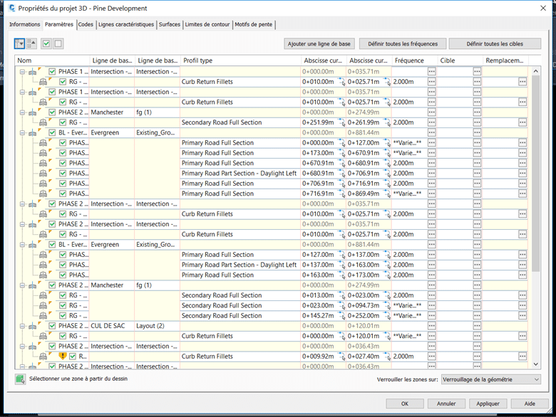
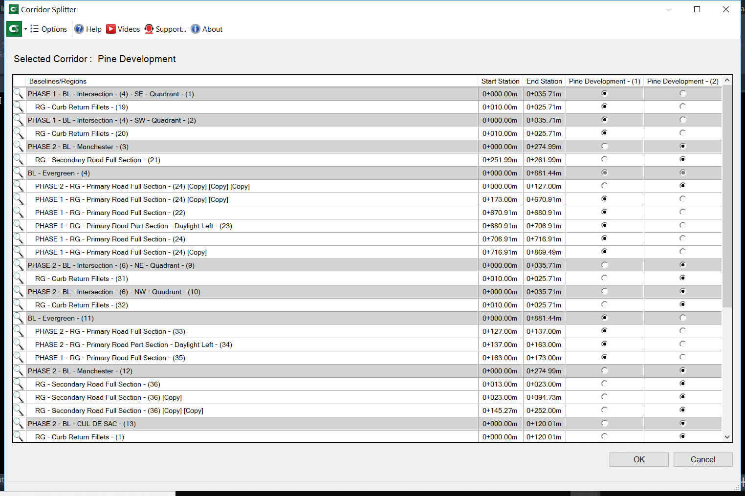
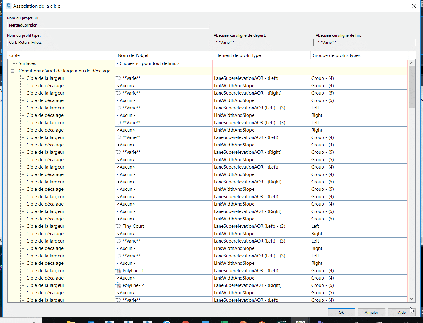
    Voici une idée des éléments à considérer et à redéfinir dans cette séparation (et la liste peut encore être déroulée…) :

    L’outil Splitter permet de diviser en deux parties un projet 3D par ses régions ou lignes de base, tout en préservant les éléments discutés plus tôt qui servent activement à définir votre conception :

    Voici le résultat final, en quelques clics :

    L’outils Merger fait exactement le même travail à l’inverse, fusionnant deux projets 3D et plus à la fois :

    Vous pouvez optionnellement réintégrer les surfaces de corridors propres à chacun des projets dans le corridor fusionné :

    Le résultat final réassemblé parle de lui-même, gardant intacte l’ensemble des paramètres de design de chacun des projets 3D à sa source :

    L’usage des cibles dans les projets 3D : un outil simple à l’utilisation complexe

    Tout design routier utilise activement des cibles de largeur ou d’élévation pour contrôler les valeurs variables des éléments de profil type (subassemblies), que ce soit pour ouvrir progressivement une voie de virage, former un cul-de-sac, former une intersection ou créer un élargissement pour un arrêt de bus.

    Dépendamment de la complexité de vos designs (en lien direct avec le nombre de lignes de bases et de régions au même endroit), la liste de cibles possibles peut être gigantesque. Peu importe sa taille, le concepteur passera une bonne partie de son temps dans cette interface à gérer les subtilités de son design :

    CTC Software propose une alternative dans ses outils, appelée Corridor Mapper, pour sauver dramatiquement votre temps d’association de cibles, sans avoir passer par le menu précédent. Sa stratégie optimale, en fait, est d’associer des cibles situées sur des calques ayant les mêmes noms que les éléments de profils types, et ce dynamiquement (peu importe l’évolution du projet, si des cibles s’ajoutent, une simple mise à jour du lien remodélise le projet 3D).

    Dans l’exemple suivant, j’ai un corridor avec une condition de détection d’entrée de cours pour abaisser la hauteur des bordures de béton automatiquement (en rouge), ainsi que des polylignes qui créeront des élargissements de voies (en vert) :

    Corridor Mapper liera le nom de chacun de ces éléments de profils types (pouvant être personnalisés à la guise de l’utilisateur) à toutes les cibles placées sur des calques prédéfinis :

    Si les calques à spécifier ont les mêmes noms que les éléments de profils types associés, les boutons Auto-Map Layers (en rouge dans l’image précédente) permettent de les lier automatiquement.

    En quelques clics, voici le résultat :

    Et si notre projet évolue en augmentant de taille, doit-on refaire des manœuvres répétitives pour reliées nos nouvelles cibles?

    Non! Un simple clic sur le bouton Auto-map Targets passe en revu le contenu changé sur les calques des cibles pour mettre à jour le corridor :

    Pour un concepteur, on vient de se sauver facilement « une ou deux crampes au bras » par année en termes d’actions répétitives éliminées de cette façon. Voici le résultat :

    Les outils « par défaut » de Civil 3D permettent également d’associer, à un temps donné, tous les objets sur un calque comme étant des cibles potentielles, mais les différences atouts qui démarquent Corridor Mapper sont :

    • La liaison facile et efficace de cibles sur des calques spécifiques, dans une interface simplifiée sans aller-retours entre plusieurs fenêtres de paramètres;
    • L’attribution automatisée de cette liaison lorsque les calques de cibles ont les mêmes noms que les éléments de profils types;
    • La liaison dynamique d’un calque de cible et de l’élément de profil type associé.

    Additionnellement, la fonction Corridor Cleanup permet de nettoyer les cibles d’un projet 3D en partie (soit par région, ligne de base ou même type de cible) ou en entièreté, permettant de partir sur de nouvelles bases lorsqu’on reprend un design que l’on souhaite altérer ou améliorer :

    Voilà le résultat :

    Conclusion

    Le volet Corridors des outils CIM Projets nous sauvent un temps important en réduisant les manipulations répétitives sur l’édition de nos projets 3D. Peu importe la taille, la complexité ou l’évolution dans le temps de votre projet 3D, ces outils spécialisés vous permettront d’adapter très rapidement vos conceptions en génie civil. Vos concepteurs et chargés de projet vous en remercieront!


    Pour en savoir plus sur la suite d’outils CIM Projects de CTC Software :

    https://www.ctcsoftware.com/product/cim-project-suite-2021/

    Vous trouverez également, au lien suivant, nos webinaires francophones en génie civil et infrastructures :

    https://www.youtube.com/playlist?list=PLAhehuVvm9ky6D0jDNPuUd0JQelxgv3i3