• Revit Content Management- Changing Needs for a Work from Anywhere Future

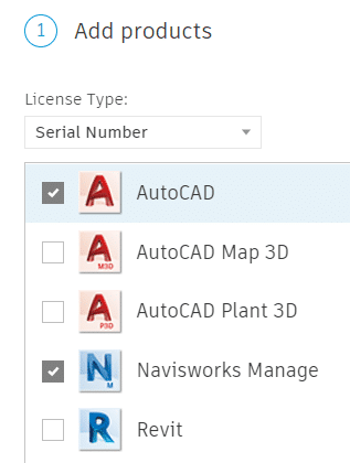
    The past year has brought challenges to all. While we look for areas to support and encourage, we continued to look at how we can best serve the needs of our clients. One of the most critical points that hit many, was the need to support entire workforces now working remotely. For our clients using Revit, Autodesk BIM 360 Collaboration enabled our clients to continue to work as teams on new and existing Revit projects. This critical piece ensured that projects could move forward. However, the Revit project models are only a portion of the solution required.

    Architects, engineers, and contractors need to author and populate these models with content. Doors, windows, beams, columns, HVAC equipment, lighting fixtures. Every piece of design content needs to be carefully selected and placed. We also need ways to manage and support these projects. Ideally helping our clients be more efficient, reducing the risk of errors and omissions, and heading off project issues ASAP.

    Dan Stine of Lake Flato Architects shared his thoughts around the important topic of content management and project analytics in this article published on the Autodesk University site. Dan explains the critical issues that CTC Software’s HIVE solution solves. SolidCAD is the exclusive provider of HIVE for Canada.

    In his article, Dan talks about the important topic of content management and project analytics and CTC Software’s holistic solution in this space, that being HIVE. He covers the importance, the challenges, disparate pockets of content, broken feedback loop, and more.

    Check out his blog post on The Necessity of Content Management and Project Analytics.

    *Dan Stine’s Bio:

    A Minnesota native who recently relocated to San Antonio, Texas, Dan Stine has nearly 30 years of experience in the AEC space. He is a Wisconsin registered architect and teaches graduate architecture students at North Dakota State University (NDSU) and presents regularly at the University of Minnesota. Additionally, he has written 14 textbooks, including six on Revit, two on AutoCAD, and one on AutoCAD Architecture. His Residential Design Using Autodesk Revit 2021 is the #1 Revit book in the academic market in North America. He also writes posts for his blog, BIM Chapters, and for Enscape’s blog. He is currently the Director of Design Technology at Lake Flato Architects, the #1 US firm on the 2019 ARCHITECT 50 List.


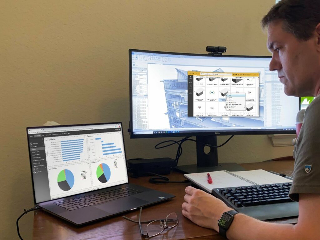
    HIVE is a content management system developed specifically for the AEC industry. Firms can organize, manage, set permissions, and ensure the latest content is kept up-to-date and available for all project participants, even when working remotely. Users can quickly find RevitAutoCAD, PDF, JPEG, and other file types quickly using libraries, tags, favorites, and file metadata.


    SolidCAD is the exclusive provider of HIVE for Canada.

    Reach out to our CTC team today. We’d like to understand more about your workflows, issues, and projects in Revit so we can continue to work towards practical solutions for our clients. 


    Matterport Capture app for Android is officially here!

    This article was originally published by Kirk Stromberg and Matterport on the Matterport Blog.

    With Capture now generally available on Google Play, anyone can Matterport their space using a Pro2 or their favorite 360 camera.

    When it comes to helping you digitize physical spaces, we’ve always believed the less friction the better. It’s your world, and we want to help you capture it.

    That’s why when we shipped our first 3D camera, we paired it with the Matterport Capture app so that anyone could download it on their iPhone or iPad and use it to scan spaces in a simple and intuitive way. As we expanded our lineup of supported cameras to include 3D LiDAR scanners, 360 cameras, and even the camera on your iPhone, the Capture app on iOS was always at the center of our user experience because we wanted to make using Matterport easy, flexible, and instantly familiar.

    Capture for Android works as flexibly and simply as on iOS, making it a cinch to connect a Matterport Pro2 or six of the most popular 360 cameras made by our partners, Insta360 and Ricoh. So if you or your company already uses the Matterport platform, the free app can be downloaded onto the compatible Android devices you already own, making it fast and easy to mobilize more people on your team to capture spaces.

    If you don’t own a compatible camera, check out the options below. The Matterport Pro2 is the right pick if you are scanning a large volume of spaces and high accuracy and image quality are important to you. If portability and affordability are key factors, then choose a 360 camera. They are a great choice for scanning small to medium size spaces. You can compare cameras here.

    Check out this video to see how easy it is to get started. And then download the free Matterport Capture app on Google Play today. We’re excited to know what you think.

    https://youtu.be/pxST9ofYshQ

    Learn more

    Below is more information on Matterport Capture for Android. Note that additional information on requirements and support can also be found on our support page:

    Minimum Requirements for Supported Android Devices

    1. Android OS – 8.X (Oreo), 9.X (Pie) , 10.X (Q), 11.X
    2. 3 GB of RAM or more
    3. Android devices certified by Google and unrooted.
    4. Modern devices with a 64-bit architecture

    Supported Cameras

    • Matterport Pro2 3D camera
    • Matterport Pro2 Lite 3D camera
    • Matterport Pro 3D Camera
    • Insta360 ONE X
    • Insta360 ONE R
    • Insta360 ONE X2
    • Ricoh Theta Z1
    • Ricoh Theta V
    • Ricoh Theta SC2

    Supported languages

    12 languages including, English, French, German, Spanish, Italian, Dutch, Russian, Brazilian Portuguese, Japanese, Korean, Chinese  (Simplified), Chinese (Traditional).

    We’ll keep on building and adding to this list, and please stay tuned for updates on Matterport for Android, giving you the ability to capture 3D spaces using just the camera on your Android device

    Label Genie for Civil 3D: New Features

    Label Genie, with it’s recent debut, changed how we do Civil 3D sheet annotation. Allowing automated insertion of labels across multiple drawings and layouts at once, Label Genie turns hours of work into minutes. The latest release will feature labeling in Profile and Section Views, and add many new label types, such as dimensions, blocks, pipe and pressure networks. Additional anchor objects will be included and new data sources will be available, such as block attributes, property sets, objects data, and more.

    In this mini video series: Part 3, our Technical Consultant Infr/GIS – Colin Gaudet will showcase how you can automate labeling in Profile and Section Views, benefit from even more label types and anchor objects than before, and more.

    For full information on CTC tools for Civil 3D click here

    Auto Grader for Civil 3D: New Features

    Auto Grader is a game-changer in Civil 3D site grading. Through dynamically linked feature line sets, users can create grading families for parking lots, ponds, subdivisions, and more. The latest release features a “template-based” grading method, allowing automatic insertion of a user-defined set of feature lines, such as a building pad, along defined baselines, such as a roadway. Other enhancements include more detailed surface targeting, automatic surface boundaries, better family preview controls, and other user-friendly features.

    In this mini video series: Part 2, our Technical Consultant Infr/GIS – Colin Gaudet will showcase detailed surface targeting, automatic surface boundaries, better family preview controls, and other user-friendly features in the video below.

    For full information on CTC tools for Civil 3D click here

    Bluebeam Revu Update 20.2

    The latest update for Bluebeam Revu has recently been released; you can find the release notes at this link.

    Independent Length Measurement units.  In previous versions, a user would calibrate a page, say in feet and inches, and all length measurements would be locked to that unit.  Length measurements can now be set to any preferred unit.  Create a measurement and change the unit in the properties.
    TIP:  if the default measurement is not in the desired unit, change the unit then set that as the new default by right-clicking.

    A refined Calibration tool.  The name has been changed from Calibrate to Set Scale.  After the tool has been launched, the dialog is a little different.  In previous versions, the Pick Points calibration window would appear first.  Now, the Apply Scales page appears first.  The user chooses either preset or custom scales, or they choose to calibrate using selected points.  Also, in this same form, the user can choose to apply the scale to a selected range of pages and add the custom scale to a preset for later use.
    TIP:  to remove a preset, click the garbage can icon in the Measurement tab.

    Earthwork Processor for Civil 3D: Subgrade Volume Calculations

    Earthwork volume calculations can be a complex task in Civil 3D, especially with variable depth subgrades found in many site projects. With the CTC Earthwork Processor in the CIM Project Suite, this work is done for you. Subgrade and stripping surfaces are created based on intuitive inputs, then results can be automatically labeled, tabled, hatched or exported to a spreadsheet.

    In this mini video series: Part 1, our Technical Consultant Infr/GIS – Colin Gaudet will give you a quick overview of Earthwork Processor from CTC CIM Project Suite and cover some of the main features and capabilities.

    For full information on CTC tools for Civil 3D click here

    Installing AutoCAD 2022 and Other Autodesk 2022 Applications

    AutoCAD 2022 is here and it has a new installer.  Very few clicks are required, which is good and easy, but what if you need to customize your installation?  Read on…

    Installers can be customized by logging into Autodesk Account.  Installers or deployments can easily be created for multiple products.

    1.Log into Autodesk Account.

    2.Click Custom Install.

    3.Choose your product(s).

    4.For all selected products, select your options:

    a. choose the version and set the serial number.

    b. Set customization options.  These include installation path, custom file paths, security settings, LISP options, Express Tools, custom profile selection, and other settings.

    5. Choose which extensions to install.

    6. Create the installer.  This downloads a small EXE file which is used to create the installer.  When run, the installation files are downloaded onto the computer to C:\Autodesk.  A Windows BAT file is created with all customized options embedded.  When run, no input is requested, the app is simply installed.

    7. This installer and BAT files can be stored on a server and run by the administrator to install the product, with its customized content, onto users’ computers.

    AutoCAD 2022 is Here

    It’s springtime and the birds are singing.  Also, Autodesk has released the latest version of their flagship CAD package, AutoCAD 2022.  Click to peruse the Autodesk Documentation. Read on to see some notes we at SolidCAD have prepared for you.

    **Please stayed tuned for the next article.  There will be important information about installing this new software**

    1. The first thing on many users’ minds is whether the file format has changed.  It has not!  We are still on the 2018 format.
    2. TRACE.  A new command enabling a safe collaborative environment to draw revisions without affecting the source drawing. Open a shared drawing in the web or mobile apps and create traces.  These traces can be managed by a CAD user in their desktop app.
    3. COUNT.  Quantifies selected blocks in a drawing and creates a dynamic table or Field.
    4. SHARE:  Shares the current drawing, with all reference files intact, to the web for others to view or edit.
    5. Push to Docs: Creates a PDF of selected layouts and saves to Autodesk Docs.
    6. Floating windows: maximize drawings on separate monitors.
    7. Redefined Start tab.
    8. New installer and options.  Very simple install.  Watch this blog page for a follow-up article.
    9. Batch publish in background uses multiple cores.
    10. Microsoft’s DirectX 12 is now supported for 2D and 3D visual styles.
    11. 3D graphics technical preview.  New 3D engine provides a better experience. It is off by default.  3DTECHPREVIEW .  Try it and provide feedback.

    Revit MEP and CTC– Schedule XL

    Having troubles keeping your MEP notes from Excel in Revit up to date? Schedule XL is the right tool for you.

    Schedule XL allows you to create schedule views (drafting view or schedule view) within Revit from your Excel worksheets. Simply create an Excel file with your MEP notes in the format you’d like and push that information to your Revit project.

    Within Revit, select the CTC Schedule XL tool and add your Excel file that you’d like to be placed in the project.

    Once added, you can override/preserve any graphics or formatting of the Excel file

    As you make your modifications to the graphics, select “OK” and Schedule XL will create a new Revit view for you. Place the view onto the desired sheet.

    As your Excel notes update and change, you can use Schedule XL  to verify if your project has the latest updated notes. Schedule XL has a “Status” feature to indicate if your Excel note files are up to date. With the “Status” showing “Out of Date”, simply click “Update” to apply the new changes.


    Schedule XL is a great tool for including outside data from other sources (Excel) to be a part of the Revit environment. With a simple Excel to Revit workflow, you can get any information across to a project with minimal effort. Schedules can also be configured to automatically update when the Revit project is opened if the original spreadsheet has changed.


    5 Revu Workflows for Civil Designers, Contractors

    This article was originally published by Troy DeGroot and Bluebeam, Inc. on the Bluebeam Blog.

    Awhile back I was teaching a Bluebeam Revu basics class for a group of civil engineers and designers. An issue quickly came up that changed the way I teach, and it was so obvious.

    I was using the same data sets in all my basics classes to show markups and measurements, but it wasn’t relevant to the civil discipline in the architecture, engineering and construction (AEC) industry. So, I quickly collected some new data sets and drew back on my industry experience to develop training tailored to those users.

    As a complement to my last post, 11 Tools to Ease the Punch Walk Process, I want to discuss five tools or workflows you may not be aware of that specifically apply—but aren’t limited to—the world of civil design and construction.

    First, let’s look at some of the differences between civil drawings and other disciplines like architectural, structure, MEP, fire, etc.

    Starting with the obvious, civil drawings are drawn at a much smaller scale. Because of the size of many jobsites, developments and roadways, drawings are showing a much larger area on each sheet.

    Also, most civil drawings don’t include dimensions or measurements. This might give some the illusion they’re not drawn to scale, but that couldn’t be more wrong. Those curvy contour lines are located very specifically.

    Obviously, everyone regardless of occupation can use the Markup tools in Bluebeam Revu to make comments on drawings and documents. I’ll skip over those and get right to my favorite five innovative ways to use Bluebeam Revu as a civil designer or engineer.

    Overlay satellite imagery

    Whether you do a screenshot or some other method for acquiring satellite images, be sure to include the scale in the image. This will make it easier to calibrate the image. If the scale isn’t available, you’re still in luck. Maybe you know the curb-to-curb dimension or a building footprint; you can calibrate from that also. Once you have the image calibrated, you can start to overlay markups for easements, utilities, signage or even site staging material and equipment. If you’re doing resurfacing or flatwork, you could even do material estimates.

    Calibrating Plan & Profile drawings with different X-Y scales 

    If you’re working with plan and profile drawings for roadways or power distribution, often the horizontal scale is drastically different from the vertical scale, making it difficult to rely on any accuracy in measurements. In the Measurement Panel in Revu, you will find the ability to calibrate the X and Y scales separately. Now you can do measurements and allow Revu to do all the complicated math for you.

    Ideas for Cut & Fill calculations

    The contour lines on a civil plan represent the vertical grade change. Depending on the size of the plan or map, this could be one foot or 1,000. To estimate cut and fill quantities, you can create volume measurements using those contours and average depths. (Maybe this video will explain it better.)

    Combining several PDFs into one large area map

    I’ve been asked this several times from the mechanical, electrical and plumbing teams as well. How can we do line-based length measurements when the material starts on one sheet and continues onto another?

    If you start a new PDF with an oversized blank sheet, you can use the Snapshot tool to collect portions of separate sheets, pasting them onto the new document. When using Snapshot, the image comes in at the same scale it was taken from, so you can easily piece them all together like a puzzle. I suggest grouping them once you have the puzzle together so you don’t accidentally move something.

    Bidding and tracking field survey projects 

    Maybe you have a last-minute bid due for a scanning or survey project and don’t have access to the site. Using the sequence or count tools in Revu, you can quickly mark all the locations you’ll need to perform a scan.

    Each mark represents a setup, scan, takedown and processing, allowing you to estimate the time needed. Using different colors or layers, you could assign different time estimates if you have to remove ceiling tiles or drudge through the mud to capture the required data.

    Use the same bid drawing when performing those scans on site. Quickly change the Status of the Markup to Complete and, if needed, attach an image of the equipment setup. In the field, you might even use different colors if you’re running several scanners at the same time. The more data the better, in case the scope changes unexpectedly.

    I know all these functions are possible in advanced software created for design. My intent is to show that you don’t need expensive CAD software to get information out of the PDF drawings. If you like these tips and want to see the technical steps, check out my YouTube Playlist.

    Hopefully, you’re inspired to look a little deeper into the civil workflows possible in Bluebeam Revu. How are you using Revu in your workflows? I’d love to hear your feedback or any new ideas you may have had while reading. You can find and message me on LinkedIn.