• Revit Data Corruption

    Let’s talk about data corruption in Revit. In this post I will look at these 4 points:

    1. File crashes before opening
    2. Crashes when opening a new view
    3. Looking for corrupt families
    4. Higher level investigation

    As always you should make sure you save a copy of your file for testing while trying to resolve corruption issues.

    File crashes before opening

    Sometimes a file cannot open because of a simple issue that can easily be overcome. Each of the following actions have the potential to get past a different issue. If your file crashes when you try to open it ask yourself:

    • Can the file be opened with or without audit checked?
    • Will the file open without the worksets loaded? Can I narrow it down to a specific workset that keeps the file from opening?
    • Can I open the file in a different build, or a newer version of Revit?
    • Sometimes new name allows you to bypass the issue, copy-paste file to new location
    • Isolate the file from the network save to a location where the links cannot be accessed.

    Crashes when opening a new view

    If your file crashes when you try to open or create new views, try these suggestions:

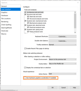
    • Turn off hardware acceleration and try each location one at a time.
    • Reset Revit settings
      • Customized settings are stored in the app data folder, when removed from this location the defaults are regenerated.
    • Repair the installation
      • This won’t change any user setting.
    • Open Revit without add-ins
      • Locate the following folder: C:\ProgramData\Autodesk\Revit\Addins\[Version].
      • Temporarily move the addin files from the folder above to another location.

    If any of these work for you take note, this is where the issue resides and you’ll want to know the exact cause whenever possible.

    Looking for Corrupt Families

    Sometimes the behavior you see in a file is caused by corrupt families follow this process to identify corrupt families.

    • Save a copy of the corrupt file
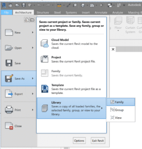
    • Open and save all families as a library, this process will fail when it reaches the 1st corrupt family.
    • Record the family named on the bottom left hand corner of the screen & delete the family and run again, repeat until the process completes successfully.
    • Open the original corrupt file and reload all the families on your list with versions that predate the corruption. If you’ don’t have a previous version of the family, you’ll need to recreate them.


    Higher level investigation & troubleshooting

    Many issues can also be fixed by returning to Revit’s original settings.  Try these steps one at a time, testing the file after each change.

    • Rename the .INI file (_old) which is in the AppData Roaming folder.
    • Rename App Data Folders (_old)
      • C:\Users\<username>\AppData\Local\Autodesk\Revit\Autodesk Revit 201x
      • C:\Users\<username>\AppData\Roaming\Autodesk\Revit\Autodesk Revit 201x
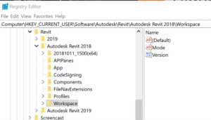
    • Rename Workspace in the registry editor

    When these folders/files don’t exist, they are recreated the next time the user opens Revit. Be sure rename and not remove these files/folders, as they will server as backups for the user original setting including keyboard shortcuts and font maps.

    Happy Reviting!

    Be sure to check my other videos in this series for more information.

    While you wait why not follow us @SolidCAD on Twitter, check out our other videos on YouTube, and see what our experts have to say on our BIM Blog!

    ___________________________________________________________________________________________________________________

    Additional Reading

    AKN: Revit – What Causes data Corruption

    AKN: Revit – Alternative Uninstall Directions

    ArcGIS and AutoCAD – Free Background for everyone using AutoCAD

    Imagine a world where you could get high resolution background image maps to display and PRINT in AutoCAD.

    Esri and Autodesk are working closer than ever and this alliance benefits all CAD and GIS users. Esri provides a free ArcGIS for AutoCAD plugin. This plugin allows vanilla AutoCAD users to access Esri maps. As mentioned, the beauty of these maps is that they also print/plot in AutoCAD.

    I was surprised at the level of detail!

    Download ArcGIS for AutoCAD plugin for free at: https://www.esri.com/en-us/arcgis/products/arcgis-for-autocad

    Contact SolidCAD for more information about our newly created three-day  training course for any INFRA, GIS/FME training.

    Revit Family Creation: Family with Adjustable Built-in Label

    Usually Tags are added separate from the Components we place, but in certain situations the “tag” needs to be part of the family. To push this further occasionally a request is made for flexibility in the placement due to text overlap.

    This post explains how create a family with a built-in label with adjustable positioning.

    Prepare the Model Family to Receive the Label

    • Open the model family that requires the built-in label.
    • Create a vertical and a horizontal Reference Line to mark the center of the default label location.

    • Create a vertical and a horizontal Reference Plane offset slightly from the reference lines. These will be the anchors for the label. Both Reference Planes must be set as “Not a reference” for the grips to show properly in the project.

    • Dimension between the new horizontal references, and the between the new vertical references. These dimensions need to be assigned separate instance parameters. To allow the label to slide in the project.

    • Choose which existing reference planes you will Align and Lock your anchor Reference Planes to. I prefer to lock them to the planes the model uses as origins. The plane you lock to must be stationary (not controlled by an instance parameter), the label will not be able to cross the horizontal anchor plane.
    • Save the family.

    HINT: To make working in a complicated family simpler follow a few best practices.

    1. Set the origin planes, then pin them.
    2. Name reference planes clearly and remove temporary planes ASAP.
    3. Dimension to the reference planes, not geometry.
    4. Flex the parameters of the family before adding geometry.
    5. Geometry to be locked to reference plans after confirming the parameters work as expected.

    Create the Label Family

    • Using the Generic Annotation Family Template, create a new “label” family.
    • Place a label, you will be prompted to create/assign a parameter to the label.
    • Edit the label type properties, so the text size & style meets the company standards.
    • Save the label & load it into the model family you started with.

    Combining the Two Families

    • Place the label family near the geometry in the project.
    • Align the horizontal reference in the label to the horizontal Reference line, and lock.
    • Align the vertical reference in the label to the vertical Reference line, and lock.

    • Select the label and Edit Type, associate the Family Parameter for the Label to the Family Parameter in the host family which will control the text, often Description or Type Comments.

    • If you have chosen to have a visibility Parameter to control the Label Visibility, associate those parameters to one another as well.

    Using the Family

    • Save the Model Family and load into a blank project to test the flexibility of the label location.
    • Select the family, the grips for the label location will become visible. Slide then around in turn.

    NOTE: Look for unexpected changes to the geometry or the overall placement of the family, this indicate the need to change the anchor alignment.

    Revisiting AutoCAD Basics: Shortcut Menu Hotkeys

    Many of us use keyboard shorts and aliases to keep our eyes on the drawing area and keep our thoughts on our design. Searching for commands on the ribbon, especially if it’s buried in the pull-down portion, is probably not our favorite things to do. The right-click contextual shortcut menus are one of the key tools for keeping ribbon searching at bay.

    Shortcut menus are great. They are fully customizable, and even out of the box they have some useful commands. What makes them even better are that each one of these can be selected with just a keystroke.

    Let’s look at the two core shortcut menus: “Default Menu”, which pops up if no objects are selected, and “Edit Menu”, which pops up if at least one object is selected.

    Default Menu:

    • R: Repeat
    • C: Clipboard
      • T: Cut
      • C: Copy
      • B: Copy with Base Point
      • P: Paste
      • K: Paste as Block
      • D: Paste to Original Coordinates
    • I: Isolate
      • I: Isolate Objects
      • H: Hide Objects
      • E: End Isolation
    • U: Undo
    • R: Redo
    • A: Pan
    • Z: Zoom (real-time)
    • Q: Quick Select
    • F: Find… (find/replace text)
    • O: Options

    So, pan command can be run with a simple right click followed by pressing A. In the above list, Isolate and Pan are nice. The rest have decent keyboard shortcut or alias options already, but things get much more interesting with the edit shortcut menu. The Edit shortcut menu hotkeys are listed below (except for those already listed above):

    Edit Menu:

    • E: Erase
    • M: Move
    • Y: Copy
    • L: Scale
    • O: Rotate
    • D: Draw Order
      • F: Bring to Front
      • B: Send to Back
      • A: Bring Above Objects
      • U: Send Under Objects
    • G: Group
      • G: Group
      • U: Ungroup
      • A: Add to Group
      • R: Remove from Group
    • D: Add Selected
    • T: Select Similar
    • A: Deselect All
    • S: Properties Palette

    Basic editing commands like copy, rotate and move are made significantly made easier with the shortcut menu hotkeys. Draw order hotkeys are solid, as are Group hotkeys (if you use the group feature). Add Selected is amazing (draws a new object of the same type and as if match properties were applied afterwards), as are Select Similar and Properties Palette.

    Best of all, whether you decide to throw more commands into the shortcut menu or not, you can manually add or edit the hotkey for each item. Let’s look at the Undo item in the “Default” shortcut menu in the CUI:

    Note how there is an “&” character in the name of the item in the shortcut menu. That designates the letter that follows (U) as the keyboard hotkey for that item.

    What this allows, essentially, is to open a second set of keyboard shortcuts that are accessed with the right mouse button.

    I know there are still many drafters who prefer to use the right mouse button to repeat the last command rather than access the shortcut menu. There is nothing wrong with that. If you are a shortcut menu user, however, it gives you all sorts of hotkeys through the right mouse button so that you can keep your eyes on the drawing area and your mind on design. Consider giving shortcut menu hotkeys a try if you don’t use them already.

    Path of Travel tool – Revit 2020

    Path of Travel tool is a new feature in Revit 2020 that determines the distance between two points on a floor plan. By selecting a start point and an end point, Revit automatically creates the path and calculates the length and the speed of the travel based on an average walking time. The tool also recognizes obstacles such as walls and furniture and create a path around these model elements. The tool will ignore some model elements such as demolished elements or elements that are hidden in the view.

    Some other categories can also be customized under the Analyze tab – Route Analysis Settings.

    Notice that by default the doors are not considered obstacles.

    You can also set an analyze zone and determine the top and bottom offset. Any object in this range will be considered an obstacle and the path will avoid them.

    Path of Travel

    To use the Path of Travel tool, open a floor plan view and go to the Analyze ribbon tab and select Path of Travel on the Route Analysis panel. Revit will ask to pick a start point and an end point.

    Once we have selected the end point, an automatic green path line runs along the building. Since we can tag the path information, I placed a tag to read the length and time parameters.

    The tool can also be updated in case we add a model element on the way. To update the path, select the path you want to update and under the Modify | Path of Travel Lines click on Update.

    Notice that it also updates the tag.

    If we select the path created and look under properties, we can find the instance properties calculated by the path. These are reporting parameters and when you modify the path Revit will redo the calculation. Notice that the Path of Travel is a detail line which means it is view specific. It is important that you create this in the view you wish to see it in, and it will not need to be filtered or hidden from other views.

    Reveal Obstacles

    This tool is very useful to figure out why the Path is not behaving properly and understand which elements are being considered as obstacles.

    After toggling it, all elements analyzed as obstacles will display in color and the rest will display in halftone. The categories can be changed at the Route Analysis settings.

    Schedule

    We can also schedule this information and set filters to analyze the content and see if it is code compliant. The Path of Travel Lines will be under the Lines category.

    Here is a sample of a schedule with all the parameters that are available. On my example I set a filter to highlight in red the paths that go over 30m.

    Filters

    We can also set filters to easily identify these paths on a floor plan view and make changes if necessary. In this example I set the filter to override the lines that are greater than 30m.

    Potential Issues

    One last thing I would like to point it out is that this path graphics are not fully customizable. We can change the line style from solid to dash for example, or create a new line style, but you cannot customize the arrow and dot at the start and end point.

    The other aspect that we cannot control is the distance the path takes around an obstacle. The calculation of this distance occurs in the background. It takes in consideration the width of a typical person and body sway while walking. If you want to read more information about the path travel calculation click here.

    Conclusion

    It is impressive in how automatic and smart the tool is. Even though there are limitations on how much customization we can do with the tool, it is very exciting the fact that it can goes around objects and that it automatically updates when a change occurs, also how you don’t have to draw the line yourself, it does it for you.

    BIM Project Suite – Free Valuable Tools for AEC

    Down below are BIM Project’s Suites best FREE tools:

    (1) Quick Select

    Gives users the ability to build or filter selections of Revit objects by specific categories or parameter values. For more click here

    Revit Filter Tool

     vs Quick Select Tool

    (2) Renumbering

    Provides a fast and simple way to renumber your rooms and doors. Auto-swapping avoids duplicates. Alphanumeric sequential numbering. Add separators and suffices to room and door numbers. For more click here

    Project Analytics with CTC Software

    Need for data analytics is growing rapidly within the AEC industry. I have clients that tell me about the work, effort, time and most importantly money they have lost because they did not understand the reasons behind a project or a model being corrupted.

    CTC Software makes tools to make sure these errors don’t occur. Specifically, a tool that logs data; Project Activity Logger.

    There are some challenges to become a data driven organization, and CTC has the solution.

    Common Challenges

    • Aggregating statistics and data of activity in on-going Revit projects
    • Detecting problems encountered as projects progress
    • Generating accurate and complete reports of current workflows, resources and expertise

    Solution – Project Activity Logger (PAL)

    • Lightweight background capture of key performance indicators for Revit projects
    • Real-time availability of data on work-shared projects
    • Data stored allows easy connection & visualization with popular business intelligence software

    Source of ROI – Return on Investment Realized

    • Flexible licensing & highly competitive pricing- get up and running with lower investment than similar products
    • Proactive and ongoing project analysis- make informed improvements before problems escalate
    • Optimize workflows, schedule resources and identify training opportunities for future projects

    If you are a data driven firm or looking to get there. Contact SolidCAD to assess your current Revit workflow and understand what other firms are doing in the industry to get ahead.

    Oneira Corporation

    Success Stories

    Oneira Corporation

    Oneira Corporation, An EPCM* Company, Is A Leading Engineering And Technology Company Providing Industrial Process And Solutions

    Based in Toronto, Canada, Oneira has more than 30 years of experience working with global leaders in the Specialty ChemicalChemical, Oil & Gas and Mineral Processing industries. Oneira has executed projects around the world ranging in size from small studies to $200 million Greenfield facilities.

    Project Profile

    Similar Projects

    H.H. Angus & Associates Ltd.

    HH Angus is an employee-owned, independent consulting firm of engineers, technical specialists and project managers. Together, they create innovative solutions for their clients’ most complex challenges to expand what is possible for a better future.

    DIALOG

    DIALOG believes that their passion for design should improve the wellbeing of our communities and the environment they share. DIALOG’s multi-disciplinary team of 700 includes architects, interior designers, structural, mechanical and electrical engineers, urban planners,…

    Cumulus Architects Inc.

    Cumulus Architects Inc. is a multidisciplinary architecture and design firm located in Toronto, Ontario. Cumulus is founded on the principles of team-based design and integrated project delivery with the belief design intelligence results from broad…

    Common Uses of Productivity Tools by Contractors

    Model Compare, in the BIM Project Suite. This tool can compare to iterations of a Revit model. Very useful to see “what’s changed” in very great detail. Thus if they are estimating, or looking for coordination issues, model compare is an excellent tool that many of our contractors use.

    Spreadsheet Link, in the BIM Project Suite. This tool can push and pull data to and from Revit and spreadsheets. Very useful in estimation processes, and also if they ever need to push commissioning/installation/facility management data back into Revit objects in a project.

    Fab Sheets, in the BIM Project Suite. This tool was actually created specifically for contractors who self-perform concrete work. If they do, or create any type of construction sequencing drawing/pour sets, this tool could be a huge time saver.

    Project Cleaner, in the BIM Manager Suite. This tool is free. It helps to clean up models coming in from other parties, blowing away things like working views, or “all views, not on a sheet” which is a common desire of general contractors. This solves a few things. One, it makes the Revit project file faster performing. Two, by blowing away all the “junk” the designers left behind, it makes navigating the project in Revit easier.

    Dim Checker, in the BIM Manager Suite. This is a really cool tool. It finds out where designers might be “lying” in a dimension.

    1. Sometimes designers and engineers do not feel they have time to properly coordinate modeled object positions
    2. Too frequently this leads to overriding dimension values in very dirty ways, mimicking the days of AutoCAD workflows
    3. Unfortunately, these are rarely found and more rarely repaired, and can cause HUGE headaches for contractors and increase risk.
    4. The DIM Checker allows these dimensions strings to be found and reports generated to allow the team to easily repair and coordinate these dimensions where appropriate

    Plotter & Exporter, in the BIM Batch Suite. This tool runs on a nightly, or specified schedule to do all your exports for you. NavisWorks, PDF, DWG, whatever else you might need, automatically.

    1. Sure, generating PDFs can happen from Bluebeam, but what about everything else
    2. DWGs, Navisworks files and others often must be exported for other consultants and partners
    3. Instead of doing this from multiple places, use Plotter/Exporter to single click export all the needed files
    4. Have them exported where you want, named how you want with the exact settings you want.
    5. Instead of manually triggering exports, try scheduling this so it can happen after hours and be ready for you when you walk in the office

    Last but not least:

    Import & Link Manger, in the BIM Manager Suite. Loading, and reloading links and imported files for coordination happens all the time. Waiting for Revit to link in everything, or to find where a link or import may, or may not be working is a pain.

    1. All too frequently files are improperly linked or imported into production models
    2. While Revit does allow minimal management of links, there is no easy way to find and fix imported AutoCAD files
    3. ILM is critical to the regular maintenance of models by finding and fixing imports and update link settings in a simple interface

    To watch our previous webinars on BIM Project Suite click here!

    Uncover CTC’s Project Cleaner tool from BIM Manager Suite

    In case you were unable to attend SolidCAD and CTC’s webinar last week here is what you need to know…

    When working through general project cleanup, there are many tedious tasks. Deleting unused views, removing imports, cleaning working schedules… the list goes on.
    Instead of doing this all manually, perhaps a free tool that can help automate this process. These are tasks we all should be doing in project models on a regular basis, and when sending or receiving models from others. Who has the time to do this without automation?

    Project Cleaner 

    • Removing user duplicated working views can frequently enable purging of unused documentation elements, reduce file size and speed model performance
    • Allows BIM manager to easily manage unwanted or unneeded views, sheets and schedules in the project without re-organizing the project browser
    • Using ‘Options’ can enable sorting of views and sheets in meaningful ways to enable rapid decision making about view use and value.

    Join SolidCAD and CTC’s Shawn Zirbes to explore Project Cleaner from BIM Manager Suite. This webinar will demonstrate how Project Cleaner from BIM Manager Suite can speed up this task for free with a simple to use toolset.
    Click here to Register