Autodesk has released the first update for Civil 3D 2021. Find official documentation here. Here are some highlights:
Feature Lines:
Easily insert elevation points or PIs on feature lines at their crossings with other feature lines.
Set grade or slope between multiple feature lines. Use the previous new command to insert points first.
Pressure Networks:
Add/Move/Delete vertical bends from a pressure network.
Pipe run profile settings:
New overrides tab for specifying static or dynamic updates.
Profiles selection now includes a create from surface option.
You can now change a straight pipe to a curved pipe in profile view by grip editing, and change a curved pipe to a straight pipe.
BIM 360 Collaboration for Civil: Support has been added for reference templates and sheet set data files. You must install the latest update for the Desktop Connector.
ArcGIS:
You can add new objects that were created in Civil 3D to ArcGIS by moving them to an existing ArcGIS layer and then saving the layer back to ArcGIS. Changes to property set data are now saved back to ArcGIS along with the geometry.
Support has been added for exporting curves (instead of tessellated segments) to a file geodatabase.
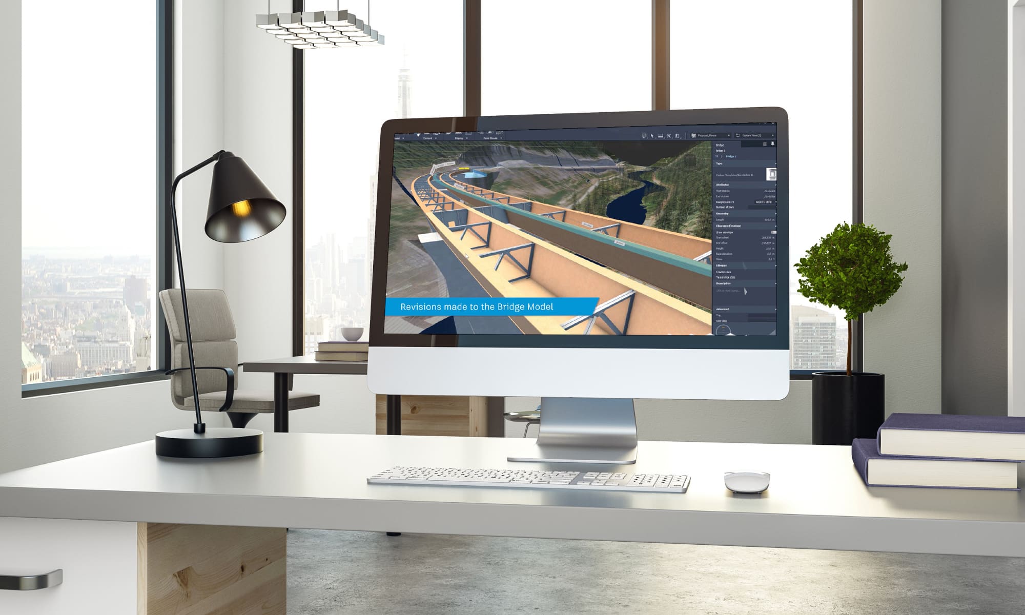
Bridges
Support has been added for configuring layers for an existing bridge in a drawing.
Support has been added for assigning layers for bridge generic object subtypes.
Project Explorer: Autodesk Project Explorer for Civil 3D is an environment that allows you to review and analyze civil objects in the model. Here we will look at Alignments, Profiles, and Corridors. See this YouTube playlist. This is an extension which must be downloaded and installed separately from 2021.1.
Autodesk has released the first update for Infraworks 2021. Find official documentation here. As of the date of the release of this article, Autodesk has not yet added information about the 2021.1 update. When they do, this link should be correct.
Here are some highlights:
New Home page. More like AutoCAD and Civil 3D.
Import complex Civil 3D corridors with multiple baselines and offset baselines.
Customize lane and intersection markings.
Model builder allows the selection of a projected coordinate system before the model has been generated.
While Enterprise resource planning and maintenance management platformsare versatile tools that can up productivity and lower operating costs, they normally offer basic engineering document management capabilities.
This can lead to users struggling to find the latest engineering documents related to assets. Without robust engineering document management tools, a business can see lower operating efficiency and ROI due to increased downtime, maintenance delays and safety incidents.
Meridian Cloud API allows you to unifyall your enterprise tools with Accruent’s industry-leading Meridian document management solution to have a complete and efficient solution.
Combining all these powerful systems will allow your business to better manage your assets and ensure that all your critical data is easily accessible, secure, a tracible throughout:
Enterprise Resource Planning (ERP)
Enterprise Asset Management (EAM)
Computerized Maintenance Management system (CMMS)
Enterprise Document Management (EDM)
How can Meridian Cloud API help your team?
The Meridian Cloud API enables integrations between your existing ERP, CMMS, or FM solutions and Accruent’s engineering document management solution, Meridian.
Meridian supplies a secure, scalable, and accessible repository for all technical and asset related documentation. This solution not only creates asingle source of truth for your technical documents, but also meets compliance needs with industry-specific regulations.
Page Break
With the Meridian Cloud API, you will be able to:
Create traceability between technical documents, assets and emails stored in Meridian
Keep asset information uniform across platforms, creating one single source of truth for data
View a list of all associated documents/information related to an asset in a single space
Reduce duplication of data across multiple systems
Out of date information and data reduces operating efficiency. Meridian Cloud API will allow your teams to incorporate workflows and data synchronization across enterprise asset tools to maximize uptime and reduce data re-entry.
Synchronize critical data across different systems
The ability to synchronize your documentation and assets between all your different tools will allow for fully integrated workflows. Having your companies’ technical documentation tiedto their respective assets will reduce downtime and lower the total cost of maintenance.
Reduce duplication of data
Utilizing multiple data repositories without sync capabilities will introduce the creation of duplicate entries which is both time-consumingand inefficient and may lead to increased opportunity for human error. This can lead to making costly decisions that rely on out of date information.
Whenever maintenance and engineering teams work out of many separate systems, it can lead to work order delays and negatively affect the safety of personnel in the field.
Meridian Cloud API integration will ensure your asset data and technical documents are up to datealwaysto avoid these issues.
Unify Your Engineering and Maintenance Departments with Meridian Cloud API
Meridian Cloud API can link your ERP, CMMS or EAM platform with our document management solutionMeridian allowing for an update to date, single source of truth, and complaint Enterprise solution for your teams.
The SolidCAD Meridian team is available for your EDM implementation needs.[/vc_column_text][/vc_column][/vc_row]
Now your project is created, you will need to upload all documents needed for your project which need to be shared with your team or your partners in the project.
To do so, select between adding a folder, a file or create a new folder with its own structure
Note: In this part, I strongly recommend using the same folder organization you are using usually in your company. Remember you are creating a copy of your documents where they will be updated. It does not mean it will automatically update the folder on your computer. Only the documents stocked in Project will be.
From now on, you have uploaded your project files and you are ready to collaborate with Project. But before starting, there are some rule you will need to know in order to understand how to work with it.
How to Use Projects and Projects with Sessions
As you should know now, we are working in a document management context. It means there are a bunch of securities and processes to protect every user. Check in / check out is part of it.
Basically, when you will need to use a document, you will have 3 choices; open it for viewing, open it for working on it, open it to work on it with collaborator.
The first one does not require to check out the document. As you will not change anything, there is no need to create a new version.
The 2 others will require every user to check out the document from project to work on it and, at the end of your work, check in the document as new version in order to quickly sum up what you’ve did.
Checking out a document means you lock the document for edition to other users the moment you are using it until you check in the document in Project.
When you check out the document, it will appear on the right side of Project’s interface as Pending
Click on it and start working.
You will notice a specific icon in your document’s tab. Depending of the status of your document, the icon will change. If you click in this icon while working in a check out document, you will access a menu.
If other users try to open the document when it is checked out, they will only have the possibility to download a copy on their computer, but they will not be able to overwrite your document (unless doing so manually by the administrator of the Project).
If you need to work with other people at the same time on a document hosted in project, it’s quite simple. Just, right click on your file and choose Add to a New Session
Now, Bluebeam will launch the dialog box of Session where you will name your session. You will be able to invite people with email address in the Session interface directly to work with you.
You will run this session like you did so when you create a Session directly (without using Project) and finish it as usual.
But this time, you will need to check in the document once the session is over in order to save the new version of your plan in Project. You have two ways to do this;
Once you finished the session, the icon of your tab will change from a whiteboard to a Check Out icon .
Click on it and select Check In. Then write a comment to explain what has been done and Check In.
Or, you can go back to your project interface and do the same with your document that will be in the right side of the interface under pending.
You know now how to start and set up a Project with Bluebeam. For sure, there are some advanced options we did not developed in this tutorial (creating group with different rights in the session, make some files viewable by certain user only, synchronizing documents, Managing and supporting Studio Session and Project with Studio Prime, connect Studio Session with BIM 360 …).
But we will see that in a future article depending of your comments and feedbacks
Quick FAQ
What type of document can I upload?
All type of document. Users who would need to access these files will have to own the software required to run / open the file (except for PDF which will open in Bluebeam)
What is the limitation of Studio Sessions and Studio Projects?
Description
Studio Projects
Studio Sessions
License Required
Host only
Host Only
Bluebeam ID required (free)
Yes
Yes
Formats supported
All types of files
PDF Only
Max file Size
Unlimited
1 Gb each document
Max files allowed
Unlimited
5000
Max space allowed
Unlimited
Unlimited
Max attendees at the same time
Unlimited
500
Scheduled Expiry
No
Yes
How much time my documents will be hosted on Bluebeam server after finishing and deleting my project?
90 days maximum unless you need more time. The save on Bluebeam Cloud Server are not accessible by anybody else (not even Bluebeam employee) and has been created to let user have a chance to download their document if they forgot to do so.
Why should I put an expiry date in my session?
It’s your choice to do so. It exists to be part of a process and avoid having to bump a limit because you forgot to close a session. Remember you could use Studio with partners outside your organization. Depending of the size of your project, 500 users can be easily reach. So, you better want to organize a process to avoid the situation.
Are you a Revit MEP user and frequently download Revit content from manufacturers or sources like BIM Object? Once that content is loaded into the project, is there a struggle to get the family properly to work with your schedules? Well than the CTC Parameter Jammer tool is the one to help solve these problems.
Downloading Revit family content regularly brings along shared parameters to your project that are different from your company’s standards. This will give inconsistent information within the schedules. Use Parameter Jammer to deal with those problems.
Here is a schedule with a family loaded into a project but does not have information populated because of the inconsistent parameters from the family to the project.
Run Parameter Jammer
With a simple user interface, there a couple steps needed to map the loaded family’s parameters to match the project.
Select your companies shared parameter file
Select the schedule that the family will be residing in
Select the family/families that the parameters need to be modified
In the next window, you will get a list of all the Shared Parameters from the selected schedule along with the family parameters. From the family parameter list, you will apply what needs to be done to the family. Parameter Jammer will also find same named parameters and automatically map them. When you select the drop-down list, you specify a family parameter to match the ones in your schedule. It will only show parameters that have the same units. You can also create a new instance or type parameter for the loaded family.
A final report will be displayed to show what has been done.
As you can see, downloadable content being used in a project does not need to have much modification for it to work properly in your current projects. Parameter Jammer gives you the ability to quickly grab information from the new loaded families and map those parameters to meet your company standards. Your schedules will be up to date and have no missing information in a matter of a few clicks using Parameter Jammer.
Revit 2021 comes with many new features and improvements. I have highlighted some of the multidiscipline Revit features in this post.
User Interface feature
As soon we open Revit 2021 for the first time, we notice an improved Home screen with an User Interface Wizard to help us set up the ribbon based on our discipline and focus on the tools that matters to us. You can also modify the user interface in the Option menu.
Generative Design
Revit 2021 comes with a Generative Design tool designed to help us taking advantage of computing power and quickly generate and explore design alternatives which can helps us to solve design problems.
With this new tool, you will be able to specify constraints, set your goals and inputs and then automatically generates design iterations directly from the model.
Credit: Autodesk
Change the appearance of a Schedule
In Revit 2020 there is a tool called Stripe Rows but we can’t choose the color and it is not visible when placing the schedules on sheets.
In the Appearance properties of a schedule in Revit 2021, there is a new feature that allows us to add stripped rows and choose a color making it easier to visualize schedules. There is also a check box to turn on the stripe rows on sheets.
Enable View Filter
In the Visibility/Graphic Overrides dialog, under Filter tab, we can turn a View Filter on and off without needing to delete it from the list using the Enable Filter command. It differs from the Visibility command which turns on and off all the elements in a view.
Slanted Walls
When selecting the walls, there is a new parameter added called Cross-Section. This parameter allows us to change from Vertical to Slanted walls. When set to Slanted, the Angle from Vertical parameter becomes available. By default, the angle is set to 0 degrees. You can add a positive or negative angle which will slant the wall to exterior or interior.
The windows and doors hosted in slanted walls can be modified by changing the Orientation parameter from Vertical to Slanted.
Real-time realistic views
The new Realistic visual style provides a better visualization and better navigation. See image below.
PDF and image linking
In Revit 2021 allows us to link PDF files and images. With this new enhancement, the linked file can be reloaded when the referenced file is modified.
The Manage Links dialog has been updated as well and now includes a PDF and an Image tab. Now we can use this dialog to find the image/PDF in the file using the Show button, place an instance of an image/PDF using the Place Instance command and add a new image/PDF using the Add… tool.
Rotate Text in Tags Enhancement
The family parameter Rotate with Component in the family editor has been added to more tag categories including furniture and specialty equipment for example. For a full list of the categories check Rotate Tag with Component.
Get Autodesk Content
During the installation, Autodesk is not providing all content. Users can download the out-of-the-box content using the Get Autodesk Content tool on the Insert tab.
Conclusion
This is some of the new features in Revit 2021. To learn more about these features and much more, check the Autodesk website.
Studio Project is a cloud-based light document management system that allows people to centralize and access their project data using Bluebeam Revu Interface. Files within Studio Project can be checked out for editing (ex: revisions) and checked back in to create different version of a single document instead of creating multiple duplicate of the same or, overwriting important data.
Before Starting
1ST STEP – Create a Bluebeam ID
In order to be able to use Bluebeam Studio services, you need to create a Bluebeam ID. It’s free and simple.
Basically, open your Bluebeam Revu, then go in Bluebeam Studio section and click on Sign In
Right after, the following dialog box will appear fill the form and finish by clicking on CREATE AN ACCOUNT button
You will have to review the terms of use and click the I ACCEPT button if you agree with these terms. A confirmation email will be sent after to confirm your Bluebeam ID.
Check your email (and spam box if you don’t see the email in your INBOX after 5 mins) and confirm your Bluebeam ID.
You are now set to start using Bluebeam Studio.
Part 1: Creating a Project
As previously written, Bluebeam Studio Project acts as a single source of truth for all your project documents. So, to maintain this statement, you will need to be able to understand what you can or cannot do with Studio Project. You will also need to know how to set up a project, to configure permissions and to share the information internally or externally.
To create a new project, go to Bluebeam Studio section and click connect. From there, you have 2 options: creating a Session or creating a Project.
Now, select Projects and then, click on the + (add) button (as circle in red) and select New Project as shown in the picture below
After doing so, a dialog box will appear, and you will be asked to name your Project
Easily differentiate points appropriate for a surface model from those that are not.
A typical topographical surveys consist of hundreds or even thousands of points, most of which must be added to the definition of a surface model. Some of these survey points are not appropriate for use in defining surface models. Such as those points not taken on the ground.
Many Civil 3D users use a special point group to exclude those points that are not appropriate for surface models. The group is defined by including the survey points, but excluding those points whose raw descriptions match those in the list.
This works well, but it will fail when the surveyor shoots a point with a non-standard code, that point does not belong in a surface model, and this is not communicated with the design staff.
Consider this technique instead: Define description keys for all points and define the Format column as usual with one exception: add a special character, such as a plus, to the end of those points which are appropriate for modeling surfaces. Points that are not shot on the ground are devoid of this plus at the end.
Then define the point group with only one custom setting, Include points whose Full Description ends with that special character, in this case a plus.
When a surveyor in the field encounters a feature which requires a new code, and that point is appropriate for a surface, they can simply append that special character to their raw description. If no communication between them and the office staff takes place, that point will automatically be included in the point group and therefore in the surface model.
In the rare case where a point normally appropriate for a surface model is not appropriate for a single shot, the surveyor can append another special character to exclude that point from the surface. MHD- Then the surface point group can exclude points whose raw description ends in that character.
Many industries have been affected by the Covid-19 Pandemic including Manufacturing, Utilities, and Transportation. As projects need to stay on track despite today’s challenges, we have all had to assess our normal collaboration strategies to focus on remote work and staying effective.
Common questions that arise with so many employees working from home:
How do we collaborate with both our internal and external partners as we work from home without our usual access to our full suite of tools?
How do we confirm the accuracy of information received from external sources?
Do we have controls and workflows in place for project document sharing?
Some companies have adapted quickly to the remote work reality as they have modern SaaS tools in place. They have had little impact on their day to day operations.
Others are struggling to shift to this new paradigm. They are now forced to look for new collaboration tools to empower their employees and minimize downtime.
When searching for the right capital project management tool the following questions arise:
How do we track project progress and meet compliance standards?
Can we control, digitize, and monitor tasks in our typical project workflow?
How do we provide access to all technical documentation to various stakeholders?
Is there a tool that is easy to learn and to use for rapid user adoption?
A SaaS EDM application will tick all these boxes and provide the ideal solution to keep your projects on-time and your customers informed.
Available in either SaaS or Cloud-based offerings, an Engineering Document Management (EDM) suite will provide the following instant benefits:
Web-based access to allow maximum flexibility for remote external and internal stakeholders.
Bi-directional updates to engineering documents and drawings with full workflow support.
Mobile access to all documentation which leads to increased employee collaboration and efficiency.
A SaaS-based EDM solution will provide an adaptable tool for your remote workforce needs. If you have not implemented an EDM solution, now is the time.
Accruent’s Meridian Cloud connects Engineering, Management, and Maintenance teams to ensure all documents and asset data are compliant and up to date.
We use the Manage Tab in Civil 3D for some important stuff like data shortcuts, managing styles, and Dynamo. But how often do we look at the panels between those tools?
So today let’s talk about Property Set Data.
Property Sets are a great tool to attach additional information to any AutoCAD or Civil 3D objects in your projects. They are pretty easy to use and incredibly versatile.
Property Set Data can be set up in a drawing (DWG) or in a template file (DWT) so that it can be brought into each new project. The opportunity to have these in a template is often overlooked, but can offer a nice solution for adding data to objects and aiding in the transfer of information throughout a project’s life cycle.
When you select Define Property Sets in the Manage Tab, it will bring up a filtered style manager window where you can create Property Sets, determine what objects they can be applied to, and add definitions.
While pipes have a lot of meta data behind the scenes, utilities are often drawing using Feature lines or Polylines. Layers absolutely give us some information as to what these lines represent, but property sets can take this transfer of information to a new level. In this case we can ensure consistency across revisions and eliminate dangerous assumptions about existing utilities.
There are several ways to add definitions to your property set, but all of the definitions above are manual property definitions. The type of definition will restrict the value input options for the user. There are many types of inputs from plain text to True/False options to integers or even predefined lists that we can use to get useful and quantifiable data added to any object.
In your drawing you can select multiple objects and add a Property Set to them all at the same time in the Extended Data Tab of the AutoCAD Properties window. Likewise, we can remove a Property Set from multiple objects at the same time. Then depending on the data type, you can pick from a dropdown list or enter a year of installation to add important information needed for the project design.
From the additional information I added, not only can we see what these polylines represent, we also have a better idea of how accurate this information is. Knowing that this utility information was confirmed through daylighting gives me much more confidence that it is 75mm conduit, or that it is even drawn in the correct location.
This custom meta data stays with these objects and can be leveraged in other applications like NavisWorks or Infraworks.
Or we can manually code our own label styles to sit in the template with our property set
<[PS:Property Set:Definition Name]> Keep in mind this is case sensitive.
Or we can create a Schedule in the template to show this information in table form. Creating schedules is a little tricky and somewhat hidden in Civil 3D, but using the command < SCHEDULE [Style] > we can create a schedule style. Then < -SCHEDULEADD > we can create a schedule of this data.
This information can also be linked to Microsoft Excel and Microsoft Access for more flexibility.
Hopefully this example has shown you some of the flexibility of Property Set Data. But this is only the tip of the iceberg when we look at the possibilities that come with creating these customized properties for objects in our designs. So get creative with these tools and use them to streamline communication, minimize errors and assumptions, and create more informative designs.
Here are a couple useful commands to speed things up when working with Property Sets:
AECPSDAUTOATTACH – Automatically attaches all property set data to all the objects they apply to in the drawing. Also allows automatic updates if property sets are edited.
PROPERTYSETCLEAN – Use when AECPSDAUTOATTACH is OFF. Updates property set information associated to objects after edits have been made to property set data.