• AutoCAD 2023: New Release

    AutoCAD 2023: New Release

    It’s that time of year; Autodesk has just released the 2023 version of their flagship drafting application, AutoCAD.  Read on to discover some of the new features.

    Click to peruse Autodesk documentation.

    Compatibility

    Likely one of the most common questions is about compatibility.  AutoCAD 2023 remains in the 2018 format.  There is no need to save files to previous versions unless your recipient is using 2017 or earlier.

    Markups

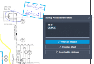
    I’m intrigued by this feature more than any other this year. PDF markups are ubiquitous in our industry, but there were few tools to help manage them.

    In AutoCAD 2023, PDF markups can be overlaid and displayed more easily, and they can then be imported as a trace layer and converted to AutoCAD objects. Markup assist will use text recognition to add AutoCAD text, multileaders, and revision clouds from the PDF markup. Image file formats are also supported if the PDF is scanned and marked with coloured pens.

    Insights

    Machine learning provides tips and tricks when and where you need them.  AutoCAD generates macro insights based on your unique command usage.

    LISP

    LISP apps can be loaded and run within the AutoCAD web app.

    General

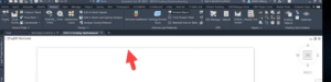
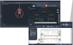
    The command line is visible within each active floating window.

    Count has been updated to enable easier navigation and selection.

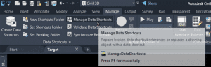
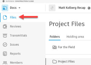
    The Sheet Set Manager has been given a performance boost and has a new interface in Autodesk Docs.

    ANNOSCALEZOOM controls mouse zooming in paper space.

    MTEXT objects can be converted to MultiLeaders.

    TRACE is now available on AutoCAD desktop, not just in the web app. You can contribute to other users’ traces.

    2D Graphics performance has been enhanced. Zoom and pan performance has been increased up to 50 times with many true type text objects, long polylines, and solid hatches. 

    The new TRAVERSALTHREAD system variable controls this.

    A new 3D graphics system (GSF) has been introduced and it promised to increase performance.  GSFENABLE is the new variable that controls this. It is ON by default. To experience the benefits of this, use the visual styles named Shaded or Shaded with Edges.  FASTSHADEMODE is a new variable that controls this behaviour.

    CUTBASE is a new command (Cut with base point found in the right-click menu) to allow the selection of a base point when cutting objects from a drawing.

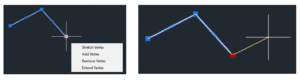
    Add a new vertex to the end of a polyline with the extend vertex option

    Tool Palette: Open File or Web Page

    Tool Palette: Open File or Web Page

    Do you have CAD standards document or web page you’d like to make easily accessible to your AutoCAD users?  Does it make sense to create a Tool Palette button for this?  If so, read on.

    Create a tool palette as usual or edit an existing palette.  Add a new tool to it, such as a line.  It will look like this initially.

    Edit the properties of that tool and change three things. Reveal your inner artist when creating the icon image. Right-click to change that image.

    Change the command string to do what you’d like the tool to do.  The syntax depends on whether you’d like to open a file or a web page.  The startapp function will use the appropriate Windows app for the selected file type.  In the example below, the PDF will open in Bluebeam Revu because that is my computer’s default PDF application.

    You’ll notice I have no path defined for the PDF.  The findfile function looks for the file in the AutoCAD Support File Search Path (AutoCAD Options).  As long as you have the intended path defined here, the file will be found.  The path to the file can most certainly be hard-coded if you prefer.

    To open a file:

    (startapp (strcat “explorer file://” (findfile “The Actual File Name.pdf”)))  If the findfile option is appropriate)

    (startapp “explorer file://c:/temp/The Actual File Name.pdf”)  If the hard-coded path option is appropriate)

    To open a web page:

    ^C^CBROWSER;https://www.solidcad.ca/services/;

    My command string looks like this for the PDF option.

    Here are my two buttons.

    Enjoy!

    Civil 3D: New Geotechnical Modeler

    Civil 3D: New Geotechnical Modeler

    Autodesk has released a new extension for Civil 3D 2022 called the Geotechnical Modeler.  It replaces the former extension named the Geotechnical Module, which was developed by Keynetix and acquired by Bentley.  The last version of the former extension worked with Civil 3D 2021.

    Today, Autodesk delivered a webinar outlining the functionality of this new extension.  If you missed it, you can watch the recording here.  There is also a short video here on YouTube.

    Here is the online help document.


    Once installed, you’ll find sample data in this folder %PROGRAMDATA%\Autodesk\C3D-GeoTechModeler-2022\SampleData.


    Matterport – Accelerating the AEC Industry

    Register for Space Jam, the Matterport event series that showcases how our partners enhance Matterport offering and provide your customers with immersive experiences

    Blog Source: Matterport

    Architects, engineers, and construction professionals are quickly discovering the power of Matterport digital twins through every stage of their project cycles. Capturing and leveraging a digital twin ensures a solid project foundation, and as professionals across the AEC industry understand, a strong foundation is vital to the success of each and every project.

    With that strong foundation, Matterport has continued to grow and evolve while staying laser (level) focused on the needs of end-users. We recently released a Notes feature, which is especially useful when several stakeholders, from a team of architects to a GC, are looking to make project updates or callouts. Notes supports a high level of collaboration across teams and projects, but is just the start. While Matterport supports notes, measurements, and even a scan-to-BIM file add-on for users, Platform Partners have taken digital twins to the next level.

    Explore the offerings below and join us on February 24 for Space Jam, the Matterport Platform Partner Demo event.  Learn how Partners can transform the way you work. Bring your questions because Partners will demo their products and stick around for live Q&A. Come ready to vote on your favorite presentation!

    Do you need to censor something in your Matterport Tour, say a family photo, signage, license plates? Inside your Matterport Account, in the Edit Mode of a Showcase model, is the Blur Brush.

    The Blur Brush is brand new and we couldn’t be more excited to show it off. Many of you have been patiently waiting for this tool to help boost privacy and control over what to hide in your Matterport spaces. This, however, is only the beginning. What Amir covers in this video is only version 1.0 of the Blur Brush. As the tool develops, we’ll be adding new videos and linking to them from here.

    Register here: https://my.matterport.com/settings/account/manage


    e-Building

    Beyond powerful tools, e-Building allows users to manage all their BIM models on a single platform and connect them to Matterport models. Upload Revit, SketchUp, Autocad and Inventor files as well as .IFC, .Stp files, point clouds and more. View, section, examine, share and associate files with a tag of the Matterport model and display them in the e-Building DataBox.

    AEC 1


    Use this solution for:

    • Tag management
    • Smart document management
    • Model extension
    • BIM Model management

    Register here.


    Nspect takes 3D data and creates layers on top that show what your team needs to see. This could be an inspection report, a quality control review, safety inspection, or a work plan for a site on how to repair and maintain a property. With their API, you can take this 3D data and place it in the tools you use every day, or keep it with them and have complete, instant access to the issues that your teams need to address.


    AEC 2

    Use this solution for:

    • Virtual site inspection
    • Maintain safety requirements

    Link to site: https://nspect.net/

    Register here.


    RemSense

    RemSense has developed an industrial software package that uses Matterport as the image fabric that is overlaid with layers of information from client management systems. RemSense combines, adapts, modifies and implements existing and new technology to deliver solutions that solve complex engineering challenges.


    Use this solution for:

    • Building your industrial metaverse
    • Asset Augmented reality
    • Asset management system visual navigation
    • Virtual asset identification and audit

    Read the Partner Story 

    Register here.


    SIMLAB

    STAGES by SIMLAB is a tool used by all stakeholders to view, monitor, and compare building progress over time. Their goal is to create a living timeline of changes allowing users to view, collaborate, and solve issues throughout the full lifecycle of the property.


    Use this solution to:

    • Identify issues and collaborate on solutions
    • Draw sketches in a 3D space
    • Add notes to a project, including written, voice notes, video or files

    Read the Partner Story

    Register here.


    Maybe you are new to Matterport, a long-time user, or find yourself someplace in between, no matter the case, we have partner offerings that will extend the value you provide to each and every project under your management.  Matterport Platform Partners will help drive your business toward the next level of innovation. Join us on February 24, 2022 for Space Jam, where you will gain access to the solutions that will provide your customers and teams with transformative tools. Bring an open mind, and your questions, plus vote on your favorite presentation during this Matterport Partner AEC focused demo event.

    REGISTER HERE!


    Civil 3D: Edit a DREFd Object with No Source

    Civil 3D: Edit a DREFd Object with No Source

    You have a drawing containing an alignment that was data referenced. The source drawing cannot be found, and you need to edit that alignment. How to do this? Read on.
    Here you see the broken reference. The alignment can’t be edited or promoted.

    Follow these steps:

    1. Export the alignment to a LandXML file.
    2. Start a new drawing and import that LandXML file.
    3. Create a Data Shortcut to that alignment in the new drawing.
    4. Open the original file and replace the existing alignment with the new Data shortcut. There is no more broken reference; the alignment source is now the newly saved drawing.

    5. Open the new drawing and make your edits there as you normally would, remembering to synchronize the DREFs.

    Enjoy!


    Autodesk Docs: Public File Sharing Links

    Autodesk Docs: Public File Sharing Links

    Do you use Autodesk Docs?  Would you like to create a link for an external customer to download a file?  Does this customer NOT use Autodesk Docs?  If so, read on.

    Public link creation in Autodesk Docs is off by default.  This means that your recipient must own Autodesk Docs and be logged in to view or download a file you have shared.  You’re presented with this option when sharing a file or folder by default.  Note the disabled public link option (Anyone with this link).

    To enable public links, go to Doc and Files.  Then click on Settings.


    Once enabled, here is how the sharing form appears.  The public link option is enabled, and the link can be copied and sent to anyone.

    Enjoy!

    Civil 3D: Sharing Assemblies

    Civil 3D: Sharing Assemblies

    So, you’re the technical team lead for your Civil Engineering firm, and you need to share amongst your team some Civil 3D Assemblies.
    You know how to create an AutoCAD tool palette, and you know that this is the best place to share assemblies – but you’ve tried, and it’s not working.

    If you’d like to learn how this is done read on.
    Palettes can be exported and then imported onto users’ machines, but when an assembly is edited, the creator must export again and then all the users must again import. This is not efficient.

    The Hard Way

    The method that Civil 3D uses to store assemblies on a palette works well, but to set it up is a bit of a bear.  Open this document to see the full details.  Here is a summary:

    • When an assembly is dragged to a tool palette a new DWG is created on your system. For my system this is:
      C:\ProgramData\Autodesk\C3D 2022\enu\Assemblies\Metric
    • You can create a tool palette with custom assemblies, sure, but you need to make these drawings available to your users. Usually, this means copying them to a network shared folder.
    • Even when you make them available, the DWG path must be defined in an ATC file that defines the palette, This is XML programming language and it can be difficult to find and disastrous if an error is made.

    The Easy Way

    I won’t say this is “The Best” method, but I believe it to be the easiest, quickest, and most foolproof method; and it’s the one I choose to use at this time.

    I won’t go into detail about how to perform each of these steps; it is assumed you know the technique. The short answer is that each assembly will reside in its own DWG file and that file will be stored in the shared network folder. That file will be a block in the tool palette.

    Open a drawing that conforms to your Civil 3D standards. Possibly one that already contains your desired assembly. 

    1. If the assembly has yet to be created, create it. 
    2. Ensure it is on the desired layer. Assign the desired code set style to it. Move it from its insertion point to 0,0. If this last step is skipped, the assembly will not be inserted properly later.


    3. Save the drawing to your shared network folder.


    4. WBLOCK and select the assembly and subassemblies together.  Ensure the insertion coordinates are 0,0,0 and provide the file name.  Click OK to create the drawing.


    5. Create a new tool palette or set current the destination palette for your new assemblies.  Drag the newly created drawing into the palette.

    6. To use the new assembly, drag it from the palette into a new drawing.  This will be a block, however.  It will need to be exploded once.

    7. You may suggest turning on the Explode option in the tool to avoid the explode step.  Indeed, I thought of that as well.  Problem is, this is what you get!


    That’s it.  Once the assemblies have been created, it takes about 45 seconds per assembly to add to the palette.  If edits are required, simply open the appropriate DWG, make the edits, and save.


    Civil 3D Styles: Object Naming Defaults

    Civil 3D Styles: Object Naming Defaults

    So, you’re in charge of your company’s Civil 3D standards and drawing template and you’re annoyed when users don’t use the documented naming convention.  Read on to find out more.

    Users will typically do what’s easiest, especially when the heat is on from an impending deadline.  They don’t always take the time to find the standards manual and read the proper section when they’re not sure if they’re doing the right thing.

    When Civil 3D objects are created, they all need names.  We’ve all seen Alignment(12) and Surface(235).  These are terrible names!  Road A and Existing Ground would be better, respectively.  While it’s great to have a documented standard, why not have something in the users’ faces, Just-In-Time, when they are creating the objects?

    Here is the out of the box naming scheme for surfaces.  Surface<[Next Counter(CP)]>, where Next Counter would be 1, 2, 3, etc.

    The default for this can be changed in the Settings tab.


    Why not set up the default with a hint to the desired name(s)?  in this case, the user would use one of two conventions.

    • EG
    • FG Road A Corridor

    This same technique can be used for every Civil 3D object as they all have settings for default names.  I’ll let you decide on what a good default would be, but it will help your users more easily conform to your standard.  Just sayin’.

    As a bonus tip, consider creating these objects in your template with their names already defined.  When a user starts a new file using that template, the objects will already be there available to be edited and already named with pertinent descriptions.  This technique may not work for everything, but it certainly works for quite a few.


    Autodesk Desktop Connector Update

    Autodesk Desktop Connector 

    Autodesk is spending many resources getting their cloud system tweaked just right.  Yet another version of the Desktop Connector has been made available.  Read on to find out more.

    We present version: v. 15.2.0.1634!

    You may download it here: downloaded.

    Discover more about it here: Release Notes.

    Notable features are:

    • Not new, but updated:  Check your files for integrity before uploading using the Reference Explorer.
    • Navigating folders in Windows Explorer and Civil 3D is much faster.


    Civil 3D: Grading Optimization Problem

    Civil 3D: Grading Optimization Problem

    Do you have an issue displaying the Grading Optimization (GO) window with Civil 3D 2022.1 and GO 2022.2?  If so, read on.

    I have been working with GO since it arrived, but when I installed the Civil 3D 2022.1 and GO 2022.2 updates, GO failed to display once I click “Optimize”.  The windows actually appear, but only the shadow edge.


    Autodesk is working on a public fix, but they asked me to try this, and it worked.  Create a new Windows Environment variable with this name and value.

    Variable:              USE_ANGLE

    Value:                  d3d11