There exists a defect in Civil 3D where a property set list cannot be added to a label style. Read on to find out how to overcome this bug in 3 easy steps.
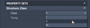
Property sets can be defined to add metadata to any Civil 3D object. In this example, structures can be assigned a class selected from a list.
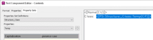
Normally, these property set data can be easily added to labels. Property set lists, however, are problematic. Note that only the Temp property can be inserted into the label style.
Here is what can be done to fix this.
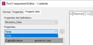
1) There needs to be a non-list property that can be assigned first. In this case, the Temp Add it to the label style.
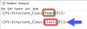
2) Copy the “code” from the editor and past it into a Notepad document and change the name of the property to the name given to the List property. In this case Class.
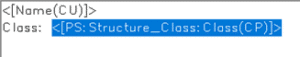
3) Copy this edited Notepad text and paste it into the label style editor.
Efficient file sharing is crucial for seamless collaboration in construction projects. In the realm of Autodesk Construction Cloud (ACC), users have access to powerful tools and features that facilitate the sharing of files among team members and stakeholders. In this blog post, we will delve into three effective methods for sharing files within ACC, namely the Design Collaboration approach, utilizing Transmittals, and leveraging the Sharing feature in Docs. By understanding these methods, construction professionals can optimize their file sharing workflows and enhance project collaboration.
There are three primary methods available within Autodesk Construction Cloud (ACC) for sharing files effectively. Let’s explore each method and understand how they can be utilized to streamline collaboration and ensure smooth information exchange in construction projects.
The first of the three Design Collaboration methods in ACC offers a structured approach to sharing files, allowing for comprehensive review and coordination among consultants before files are consumed. This method minimizes risks and ensures all parties involved have the opportunity to review and confirm the files before proceeding.
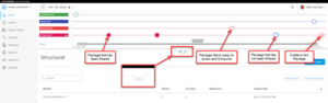
To create a new package in Design Collaboration, navigate to the top center tab and expand the timelines. Clicking on the “+” symbol at the end of your company’s timeline will initiate the creation of a new package. Within the package, you can rename the package and add and review sets which contains 2D and 3D views, as well as any models and relevant project documentation such as PDFs, Excel, and Word files.
By clicking “Share” in the top right corner, the new package appears as a circle on the timeline, indicating its availability. Other consultants can access the package, review the files, and click “Consume” to gain access to them. This method ensures that files are securely copied from the package to the shared folder, ready to be reviewed by those consultants.
Once the reviewed, consultants can click “Consume” at the top right of the screen. The act of consuming the package also fills in the circle on the timeline, providing a visual indication that they now have access to those files. As files are consumed, they are securely copied from the shared folder to your team’s consumed folder and are ready to be linked into your project.
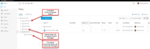
Method 2 adds a bit of risk compared to the first method as we are removing the step where the consultant reviews the documents and consumes the package. With this method, a package is created, and the files are copied to the Shared folder in the background. Instead of consuming the package, users are granted permission to view the Shared folder directly, allowing them to link files from this location rather than from the consumed folder. While this method offers more direct access to the files, it may pose challenges in terms of document control and coordination, as there is no opportunity to review documents involved.
Method 3 removes all safeguards and provides immediate access to live work-in-progress models and their updates. This method requires us to grant users permission to view other team folders, enabling real-time access to evolving models. However, it is important to note that this method is not recommended as it lacks the ability to review changes before files are linked into another team’s model. It may lead to potential rework or working in response to changes that are about to be altered, impacting project efficiency.
ACC‘s Transmittals feature provides a formal way to share files with other team members, enabling efficient tracking of sent and received files. By utilizing transmittals, project members can maintain better control over file exchanges and communication.
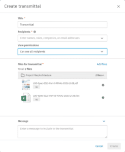
To work with transmittals, we will navigate to transmittals on the left side of the screen under Docs. From there, select “Create Transmittal” to initiate the process. Choose the files you wish to include and customize the transmittal by adding a title, specifying recipients, and including a custom message. Additionally, you have the option to adjust view permissions, allowing transparency regarding the transmittal recipients. Additional files can be added at anytime prior to sending the transmittal.
Every transmittal is assigned a unique ID and keeps track of the sender, recipient, and time of transmission. Furthermore, each transmittal includes the ability to download the files and generates a report containing vital information about the transmittal.
And lastly, within the ACC Docs feature, there are additional methods for sharing files with team members and stakeholders. These options provide flexibility and convenience in distributing project-related documents efficiently.
Sharing with Project Members allows you to share files with other project members who already have at least view-only permissions for the file. Simply navigate to the Files section in Docs, select the desired files, and click on the three dots at the top. Choose “Share” to access the sharing options. From there, you can send files to project members via email directly from ACC or generate a shareable link for alternative sharing methods. Additionally, you have the option to include a custom note in the email. You can specify whether the version of the file should reflect the latest update at the time the email or link is sent, or whether it should be the latest version when the recipient opens the email or link. This flexibility ensures that recipients have access to the most relevant file version for their reference or collaboration needs.
Sharing with Anyone expands the sharing scope to anyone, regardless of their ACC access. To utilize this option, project administrators must activate the “share publicly” feature within the project settings. Once enabled, you can share files with external stakeholders or non-ACC users. Similar to the previous method, you can choose to send an email with the files directly from ACC or generate a shareable link. Again, you can include a custom note, and you have control over the file version that recipients will access. It’s important to note that shared links expire after a specified period, typically between 30 to 365 days, ensuring that access is limited to the designated timeframe for added security.
Sharing with Another Project via Bridge offers seamless integration between projects through the Bridge feature. With this option, you can share files directly from one ACC project to another without the need for downloading and re-uploading. This not only saves time but also ensures that files remain consistent across projects. Moreover, you can specify a specific folder in your project that will automatically sync with the corresponding folder in the target project. As updates and changes are made, they will be automatically transmitted to the connected project. This feature simplifies file sharing and synchronization between related projects, enhancing collaboration and information exchange.
In the fast-paced world of construction, effective file sharing is a cornerstone of successful project collaboration. Autodesk Construction Cloud offers a range of robust features to streamline this crucial aspect of teamwork. By leveraging the Design Collaboration methods, Transmittals, and Sharing in Docs, construction professionals can ensure seamless communication, improved document control, and enhanced productivity throughout their projects. Embrace the power of ACC’s file sharing capabilities and elevate your construction collaboration to new heights.
Public transportation – buses, trains, subways, and more – have a wide range of complex assets that are both mobile and stationary. Upgrades, expansions, and new assets become intricate engineering projects involving a broad array of information and documents.
Hardcopy and manual methods for managing this information and changes are ad hoc and unreliable – causing engineers to use outdated information. This spawns rework, cost increases, schedule delays, and conditions out of specification. This chaos is brought under control with Accruent Meridian’s software for managing engineering information. As a result, projects are more likely to meet the leading KPIs for on-time, in-budget, and within spec.
Engineering information management reduces rework and helps assures completion of projects on-time, in-budget, and on-schedule.
Société de Transport de Montréal uses Accruent Meridian in its engineering teams for information management and business process automation replacing unreliable ad hoc manual methods.
Société de Transport Montréal (STM)
Public transportation has existed in Montréal for over 150 years, starting with horse-drawn tramways in 1861. Société de Transport de Montréal (STM) became a public corporation in 1951 with the mission to provide Montrealers with fast, reliable, economical transit service. The company now has over 11,000 employees.
Large Infrastructure with Complex Assets
From its beginnings in 1861, STM has grown to include four subway lines with 68 stations and over 1,000 cars. The bus system includes 186 bus routes and over 2,000 vehicles. Its paratransit service has 80 mini-buses and other taxi services for people with mobility issues. The infrastructure is widely distributed throughout the city, including rail lines, switchgear, signaling, rail yards, bridges, ticketing stations, bus stops, depots, garages, offices, and more. STM has a wide variety of complex assets.
The consultation
First used in Paris, France in 1951 and then Montreal, Canada in 1966, the passenger trains use wheels containing both rubber tires for improved traction and traditional railway steel wheels for guidance through conventional switches. Montreal has steep hills with inclines beyond the capability of steel wheels alone. Engineering projects and maintenance occur throughout the bus and rail infrastructure. The maintenance shop performs upgrades and repairs for the trains.
Substantial Investment Plan
STM’s “Organizational Strategic Plan 2025” provides a 10-year strategy, including many bus and metro projects. The C$8 billion investment plan for 2015 to 2025 focuses on improving customer transit experience. The plan initiates a shift that aims to both qualitatively and quantitatively improve the customer experience. Environmental, social, and governance (ESG) initiatives like converting to electric buses are also included.
Project Execution Barriers
The strategic plan involves many projects to engineer the design, procure materials, construct upgrades and obtain new assets. Fundamental to the success of the plan requires an examination of STM’s engineering software tools.
Engineering Project Execution
The execution of the plan involves a complex set of timed engineering projects with performance penalties if behind schedule. A study by McKinsey has shown that 98 percent of projects are completed behind schedule and over budget. Obviously, this poor performance would have a serious negative impact on STM’s strategic plan.
Large Ecosystem for Engineering Projects
STM engages with multiple contractors across various projects involving trains, buses, stations, and related infrastructure. This ecosystem includes about 20 major contractors, hundreds of smaller contractors, and their subcontractors. Individual engineers and contractors phase in and out of a project over its lifespan of 5 to 8 years.
Evils of Balkanized Engineering Data
Storing and managing engineering information using hardcopy documents in file cabinets is problematic. Engineers typically spend 30 percent of their time searching for information, which negatively impacts productivity. Too often, they also end up with older versions. Perhaps a holdover from hardcopy prints in file cabinets, each siloed engineering department stores its copy of drawings with its markups. Unfortunately, older versions of the documents are retained, and the markups are not shared.
When an engineering department edits a document or makes a change that affects another department’s records, the change stays local and is not known by others. Hardcopy documents and Adobe files in a server do not accommodate automated business processes for synchronization across silos. Manual processes – like remembering to send an email – often fail. This issue gets magnified with the ecosystem of contractors and subcontractors involved in a project. Balkanized engineering data leads to using outdated information, rework, schedule delays, and cost overruns.
Weak Information Management Compromises Project KPIs
The key cause of poor project performance involves the use of outdated engineering information and documents. This cascades into many problems, including ordering of wrong materials, fabricating components out of specifications, construction errors, and a variety of other issues. Recovery requires rework that adds costs and creates schedule delays. Sometimes the rework cannot fully bring the work back within specifications causing design compromises. The project KPIs – on-time, in-budget, and within specifications – are compromised.
Modernization Enabler
Fundamental to the execution of a project within the common leading KPIs – on-time, inbudget, and within specs – is getting all participants “on the same page” and using current information. This includes the extended enterprise comprising STM’s engineers, suppliers, and subcontractors.
Common Engineering Information
Asset information changes many times during an asset’s lifecycle, from asset creation through operations and maintenance and to end-of-life. Data about the asset are handed over numerous times from engineering, procurement, and construction (EPC) firms; supply chain partners; owner-operators; and internally within each of these organizations. Valuable data can be lost, misinterpreted, or keyed in incorrectly. Tag and equipment data are difficult to manage because they are often in differing formats, exist in various applications and systems, and transmitted by different means. Naming conventions and asset hierarchy provide additional avenues for divergence.
Managing asset information is difficult among balkanized organizations with independent workflows and KPIs. Balkanized data is often found in mutually distrusting and sometimes hostile groups or functions within an organization. This dysfunction commonly involves the design/build process for assets among the engineering, procurement, and construction functions. It also occurs during the operate and maintain phase of an asset’s lifecycle for reliability engineering, maintenance, control engineering, and others. A common repository for asset information breaks through these barriers by connecting silos to provide access to data and information. This enables an integrated view of the asset’s information, documentation, and data throughout its lifecycle across the traditionally siloed functional perspectives.
Fit Types of Users
STM organized access to the engineering data via mobility devices along three types of users:
Engineering software application user
Technician executing a work order
Casual user including subcontractors and management
Each type of user has specific permissions that fit their roles. This includes organization, locations within that organization, physical location, and permission levels. Permissions has two choices i.e., read/write access, or read only which does not permit editing.
Business Process Automation
Business process execution involves cross-functional activities. For example, a change in the maintenance strategy for an asset by the reliability team evolves into changes needed in other areas like maintenance or inspections. Manual approaches, such as email, phone calls, or paperwork orders, are unreliable, often leading to lost alerts and continuing with the old way of doing things. Business process automation ensures that the alerts go to the correct people and the needed action can be confirmed. In addition, a dashboard provides visibility to open alerts.
Meridian Implementation
SolidCAD has been partnering with STM for the last 20+ years to implement, support and train resources with Meridian.
Being the largest Autodesk partner and the only Accruent Meridian partner in Canada brought extensive value to STM, as SolidCAD has been able to deliver tailor made configurations to different engineering departments within STM. Software such as AutoCAD, Civil 3D, Inventor or even Revit are heavily used and generated file formats are handled in Meridian.
When an engineer opens a document in any of these CAD platforms, the file comes from the Meridian server for the engineering information. Saved changes also go into Meridian.
Conclusion
STM has been using Accruent Meridian since 2001. With each new project, its use expanded and now encompasses 12 different engineering departments for a wide variety of assets – buses, trains, lines, and infrastructure. It has proven to substantially reduce the use of the wrong document version and the associated rework. This also improved engineering productivity by nearly eliminating searching for information. The reduced rework and improved engineering productivity enables delivery of projects on time, within budget, and within specifications.
For further information or to provide feedback on this article, please contact your account manager or the author at rrio@arcweb.com. ARC Views are published and copyrighted by ARC Advisory Group. The information is proprietary to ARC and no part of it may be reproduced without prior permission from ARC.
Similar Projects
Énergir
Énergir, Québec's leading natural gas distributor, collaborated with SolidCAD to transition from MicroStation DGN to AutoCAD DWG, enhancing data accuracy, field safety, and interdepartmental collaboration.[...]
PROCEPACK is a firm specializing in the purchase and sale of packaging and process equipment. They serve customers from a wide range of industries from food and cosmetics to pharmaceuticals. They leverage their vast and…
Atlantis Strength is Canada’s largest commercial strength equipment manufacturer. They employ a careful balance of in-house and out-sourced methodology, and CAD technology that dictates every cut, weld, and part used during their 6-stage manufacturing process.…
With the release of Vault Professional 2024, Autodesk add two new job process into their job processor tool.
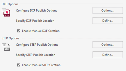
STEP and DXF are now added to the current PDF functionality. These new functionalities could be done by lifecycles states or manually on demand.
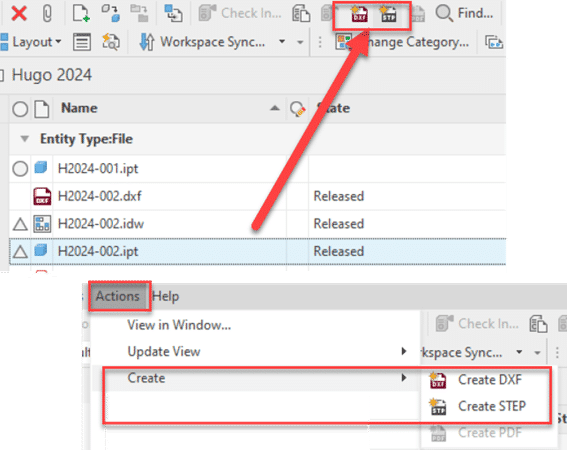
On demand function will appear into the standard Vault Toolbar or also into the action menu
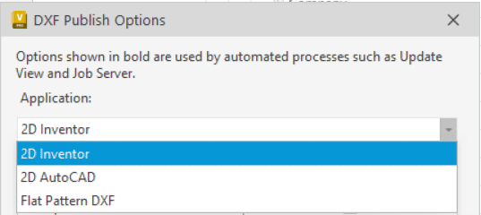
DXF Options is available for 3 file types, 2D Inventor, 2D Autocad and Inventor 3D Flat pattern.
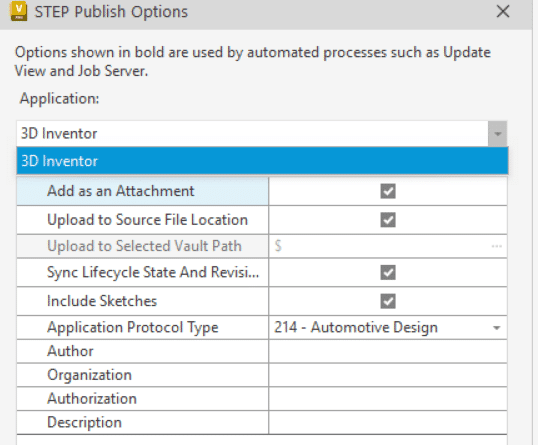
STEP file option is only for Inventor .IPT and .IAM files.
As the actual PDF option, you can specify publish options inside or outside the Vault. But take note that for the DXF Flat pattern, it’s impossible to specify a custom .ini file to generate the DXF with your custom configuration! We expect that this functionality will be added in a next available service pack or a possible workflow to modify the generic setup. I will keep you updated with another post when a solution will be available.
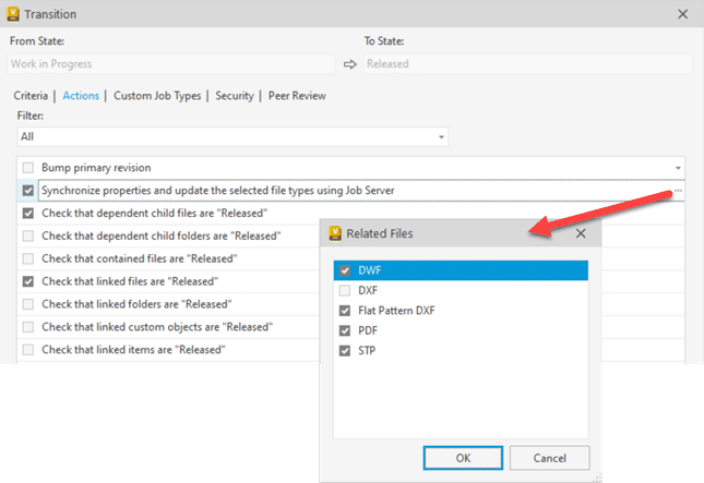
For Lifecycle change state options you will find these options into the transition action Tab and the three small dots on the “Synchronize properties and update the selected file types using the Job Server”.
Take note that if you choose the two DXF options you will have by default two .DXF files. By default the Vault naming rules are the “filename + actual file extension + .dxf”.
Ex: if you have a file name as part 123.ipt with drawing 123.idw you will have 123.ipt.dxf and 123.idw.dxf.
If you prefer to don’t have the original file extension into your .dxf, please don’t add two DXF options in same time.
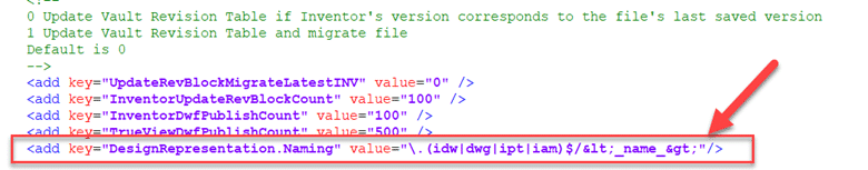
Now, how to change the DXF or STEP file naming default?
As the actual PDF, you simply need to modify or add this following line into the JobProcessor.exe.config file.
The suggested line in 1.1 will create STEP, DXF & PDF without file extension. And it will be applied for .ipt, .iam, .dwf and .idw files.
It’s why you see in yellow below the value added in the option (not mentioned into the Autodesk help) value=”\.(idw|dwg|ipt|iam)$/<_name_>”/>
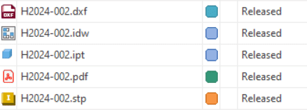
Example of the result:
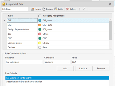
All files generated by the job processor (PDF, DXF & STEP) are Design Representation and you can easily assign specific categories to them.
All these files have a specific property because they are created by the Job Processor. The property is “Classification” and type is “Design Representation”. So if you add this into your rules and the file extension, you will be able to automate other category for STEP, DXF or PDF not generated with the job processor.
Enjoy the new tool and see more info into the Vault 2024 help!
Here’s the scene: You’re 18 months deep into building automated models and templates for your production team, and everything is working as well as you can hope – but the IT team has an upgrade plan in the works. You and your team of designers are now sporting brand new laptops, better in almost every way from what you were using before, with one small caveat: the hard drives are now a small SSD solely for Operating system usage (C:\) and a large storage drive for everything else (D:\).
To anyone who is not knee-deep in the automating trenches, this may not seem like a problem at all. You might be thinking, “Well, more space is great!”; but there’s always a ghost in the machine when you’re bootstrapping something like an automated workflow. The main challenge that I’ve seen (and have personally fallen victim to) is that users will hard-code a specific drive into their automated templates when a file path is needed – something that isn’t wrong, but can lead to challenges down the road.
So, how do we fix it? We’re going to take a look at three options, one of which you may have already considered:
Manually Changing the Drive Letter
Referencing the Drive Letter via Document Location
Referencing the Drive Letter via Project Workspace Location
Manually Changing the Drive Letter
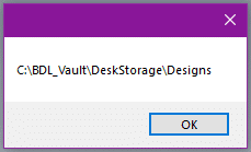
Let’s start with the simplest, but least robust choice: manually updating the drive letter in your models. Take a look at this snippet of code:
If Parameter("Location") = "Front"
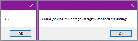
Components.Add("FRONT MOUNT CLIP", "C:\BDL_Vault\DeskStorage\Designs\Standard Mounting\133092.ipt")
Else
Components.Add("REAR MOUNT CLIP", "C:\BDL_Vault\DeskStorage\Designs\Standard Mounting\133088.ipt")
End If
This is a direct reference to a specific folder on my C:\ drive, a distinct location that I’m using to store that specific standard file. Following this concept, you would simply edit each string to look like this:
If Parameter("Location") = "Front"
Components.Add("FRONT MOUNT CLIP", "D:\BDL_Vault\DeskStorage\Designs\Standard Mounting\133092.ipt")
Else
Components.Add("REAR MOUNT CLIP", "D:\BDL_Vault\DeskStorage\Designs\Standard Mounting\133088.ipt")
End If
At this point, your template is updated. The main drawbacks to this method are that the location is still hard-coded (albeit to a new drive letter), and you will need to update each template individually each time this needs to happen.
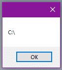
Referencing the Drive Letter via Document Location
When a file is saved, the folder path is stored as a piece of background data that is accessible via iLogic – meaning we can grab this information and pare it down to find the drive the file is stored on. A simple way to access (and display) this information is here:
The main downside to this method is that locating the drive will be entirely dependent on where you’ve saved the file that this rule is going to run in. If you have multiple storage drives and you’ve saved this file on a very specific drive (G:\, for example) then this method will return G:\ as the root drive, which may not be where you mean to look.
Referencing the Drive Letter via Project Workspace Location
This method is the most variable of the three I’ve mentioned so far, as it relies specifically on where your project file’s Workspace folder is located. The steps to get the drive letter are almost identical to the previous method, but with a slightly different input required. I’ll show you three ways to get the data we want in the snippet below:
The first line of code references the DesignProjectManager object within the context of the Inventor Application. From accessing that object, we can specify that we want to look at the current active project, and then grab the Workspace path from there.
The second line of code is the same as the first, but rather than referencing the Inventor Application, it references the Inventor Server. Functionally, this will operate the same way when run on the desktop Inventor application, but if you are eventually going to export your models to a cloud-based service (such as SolidCAD’s VARIANT configurator) you will need to reference this Server object instead.
The final line of code is the simplest, directly referencing the current document, and searching for the Workspace of the currently active project.
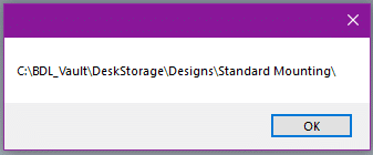
All of the above options will result in a string that looks something like this, when printed inside a message box:
Figure 4: Workspace Path
After choosing your method (I would recommend #3, personally) you can then take the same steps to get the root of the Workspace and build out your file path:
This method will ensure that you are always referencing the same drive that your workspace exists on, which is commonly where any automated templates or standard components will be located.
What Does This Actually Look Like?
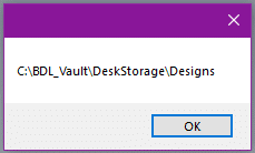
Here is an example of a very short conditional rule that makes use of the third method to locate the drive and replace a component based on the triggering parameter:
DimWSPathAsString
DimRootLetterAsString
DimStandardPathAsString
WSPath = ThisServer.DesignProjectManager.ActiveDesignProject.WorkspacePath
RootLetter = System.IO.Path.GetPathRoot(WSPath)
StandardPath = RootLetter & "BDL_Vault\DeskStorage\Designs\Standard Mounting\"
ThisAssembly.BeginManage("Mounting Clips")
SelectCaseParameter("Location")
Case"Front"
Components.Add("FRONT MOUNT CLIP", StandardPath & "133092.ipt")
Case"Rear"
Components.Add("REAR MOUNT CLIP", StandardPath & "133088.ipt")
Case"Left"
Components.Add("LEFT MOUNT CLIP", StandardPath & "133090.ipt")
Case"Right"
Components.Add("RIGHT MOUNT CLIP", StandardPath & "133077.ipt")\
CaseElse
'No Clip, should never happen
EndSelect
ThisAssembly.EndManage("Mounting Clips")
InventorVb.DocumentUpdate(True)
As you can see in context, this doesn’t add very many lines to your overall rule (even less if you initialize the variables with their end values), and it helps to future-proof your code in the case that you will be using different drives over time.
If you’d like to learn more about iLogic and how to use it, you can continue checking out the articles here on the SolidCHAT blog, or if you’re looking for a more structured or in-depth learning approach, we offer standard and custom training for iLogic and other Autodesk products here at SolidCAD.
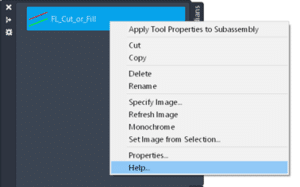
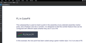
Do you create custom subassemblies for Civil 3D? PKT files? Do you write your own help files (you should)? If so, read on for this new, very welcome feature.
TLDR: In Civil 3D 2024, right clicking your custom subassembly Help button in the tool palette opens whichever help file is embedded into your PKT. In previous versions, this did not work unless you used a CHM-type of help file.
Detailed answer:
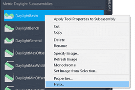
Accessing subassembly help is easy…so long as you try to get help using out of the box subassemblies, like this DaylightBasin.
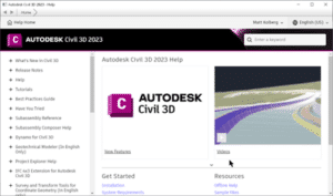
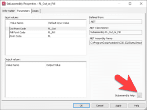
In all Civil 3D versions up to now, getting help from your custom PKT files is not as easy. Click help, like the image above, gets you this generic help page. It does not open the PDF, or MS Word file that you have embedded into the PKT. If you create a CHM file, then it DOES open. But creating these is not as straightforward as you may wish. You can get the help, but you add the subassembly and then go to subassembly help.
Now, in 2024, there seems to be new functionality that I’ve just experienced which does not appear to be documented. I developed a PKT for a customer last week and I right clicked Help in the tool palette…AND IT WORKED! The PDF opened right away.
I’ll define AutoCAD resources as files that AutoCAD uses to support design content. Here are several common file types that are customized.
Plot Style Tables (CTB/STB)
Fonts (SHX)
Printer Files (PC3/PMP)
User Interface (CUIX)
Linetypes (LIN)
Tool Palettes
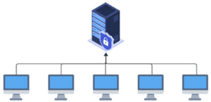
Many organizations store these files in a folder on a network-shared folder and point the users’ AutoCAD settings to this folder. This is good since there is a single location (single source of truth) for these files. When a CAD Manager updates are adds a file, users will instantly have access to it. Some firms have experienced performance degradation with this method.
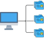
Some organizations copy these resource files to the users’ computers and use synchronization software to manage changes to them. This can be good for AutoCAD performance since the files are stored on their physical computer and not across the network. Files typically do not syn until the computer has been restarted, however.
With the Autodesk Cloud, we can have the best of both worlds. Install Autodesk Desktop Connector (ADC) v16 or later to make for the best experience. I’ll describe exactly why later in this article.
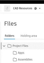
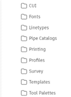
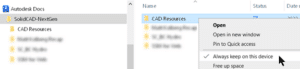
1. Create a new ACC project and invite your users to it. I named mine CAD Resources and I created subfolders for each data type. Copy your resources to the appropriate folders in the cloud.
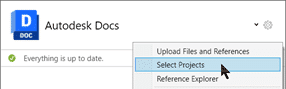
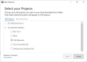
2. In the Desktop Connector on each user’s computer, ensure that this project is visible.
3. Also on each user’s computer, turn on this option for the resources folder. This is what ADC v16 is for. In v15, this was not an option. It is critical that the files physically reside on the user’s computers when AutoCAD is run. This setting ensures that.
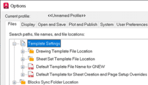
4. Lastly, configure your AutoCAD product’s settings (Options) to point to these location.
Stay tuned for the next article where printing with the Sheet Set Manager for Web uses CTB files stored in this same CAD Resources project.
D-Wave Quantum Inc. (D-Wave) is the leader in the development and delivery of quantum computing systems, software, and services. It is the only quantum computing company building both annealing and gate model quantum computers and offers quantum systems, cloud services, application development tools, and professional services to support the end-to-end quantum journey. From its inception, D-Wave has focused on delivering products and services that provide the fastest path to practical, real-world quantum and quantum-hybrid applications with customer value. Its solutions are used to tackle optimization problems spanning a multitude of industries, including manufacturing and logistics, financial services, life sciences, retail and many more. Its broad portfolio of enterprise customers—such as Mastercard, Volkswagen, Pattison Food Group, DENSO, Toyota, BBVA, NEC, Deloitte, and Lockheed Martin—have built hundreds of early quantum applications in diverse areas such as resource scheduling, mobility, logistics, drug discovery, portfolio optimization, manufacturing processes, among others.
Improving Bill Of Materials Management And ERP Integration With PLM
The Challenge
As a leader in the development of quantum computing systems, D-Wave prioritizes building high-quality systems, software, and services for its customers. With growing needs for increased cross-enterprise collaboration and heightened demand from customers, D-Wave recognized that it needed to improve its current Product Lifecycle Management (PLM). It was particularly looking for a solution that would increase the efficiency of its processes. D-Wave required to solve the following challenges in order to meet its business goals:
Bill of Materials (BOM) management and collaboration.
Manual BOM and data input into ERP.
Lack of integration, automation, and API capabilities of the system in place.
Manual change control and change management.
The Solution
SolidCAD and D-Wave teams worked closely to create the best strategy that would meet D-Wave’s business requirements. The solution was to:
Create a bi-directional integration between Fusion 360 Manage and NetSuite ERP.
The Results
Today, D-Wave uses PLM to manage Supply Chain, BOMs and Changes. The live and bi-directional integration between PLM and NetSuite ERP allows D-Wave to gain efficiency and ensure consistent knowledge-sharing by using PLM as the single source of data. The result of SolidCAD and D-Wave’s collaboration was a solution that allowed D-Wave to:
Replace its existing systems with Autodesk Fusion 360 Manage PLM, one modern centralized platform.
Manage BOMs and supply chain needs.
Streamline the management of: Vendors, Vendor Part Numbers, Manufactures and Manufacturers Part Numbers.
Centralize Change Management processes. PLM has empowered D-Wave to proactively keep track of changes.
Make more informed decisions by having access to all the necessary data in one location. The integration between NetSuite ERP and PLM has enabled the engineering and purchasing teams to increase their work efficiency
Testimonial
The main increase in functionality we have seen is the synchronization of the Fusion 360 Manage PLM database with our ERP database.
The ability to add custom filtering to searches is much superior to our old system. For example, I can look for parts I created in the last 43 days that have the word “Nut” in the description and are not released to production.
As it comes to time savings, we were able to:
Configure the part numbering system to match our existing method, saving thousands of hours of engineering work.
Remove around 8 manual processes/workarounds with Excel to move data around and supply data to our engineers.
Configure the Item Master sheet to be able to see all the fields that our engineers care about on one screen. No more flipping back and forth between tabs or scrolling up and down.
As it comes to ERP integration, automation with scripts were able to help us with:
On-Creation of a new part; automatically pushes the data to our ERP system.
On-Save of a pre-release part; automatically pushes the data to our ERP system every time we edit a part.
On-Transaction-in-ERP: pulls data on quantity, on-order, price, and stock location from our ERP back to Fusion. No need for a second license to get the information from the ERP system.
Third party middleware: link the two databases bi-directionally. No waiting until midnight for them to sync up.
Add-hidden fields for database internal IDs: the middleware can make changes in the other database directly.
Links between the part supplier and part manufacturing workspaces to allow them to be linked together and pushed to our ERP system.
As it comes to Engineering Change Order (ECO) process:
Creates very simplified part release that allows for low overhead to our engineers and enables very fast prototyping.
Creates more complex workflow for released production parts and assemblies
– Dave Bruce, Principal Mechanical Engineer at D-Wave
Products & Services Used
Fusion 360 Manage.
Implementation, Integration and Project Management.
Post Go-Live Support.
Similar Projects
3D-P
3D-P consists of a team of mining and positioning technology experts. It was created to bring innovative thinking and new technologies to the mining industry. They have since evolved to bring this approach to several…
Starline Windows is an industry leader in the design and manufacturing of architectural aluminum window systems, as well as residential vinyl windows and doors for over 50 years. They have completed thousands of contracts and…
CMAC-Thyssen Mining Group is a contractor and mining equipment manufacturer offering a diverse range of fully integrated services with contracts carried out across multiple continents and over 850 employees worldwide. CMAC-Thyssen Mining Group makes the…
The Autodesk Desktop App (ADA) gets installed on users’ computers when Autodesk applications are installed. Its purpose is to read which Autodesk software is installed on the user’s machine and provide information about which updates and add-ins are available. It uses the user’s Autodesk login credentials to determine what applications and services to which the user is entitled.
March 16, 2023, a new Application, Autodesk Access (AA), was made available which will replace ADA. Read this Autodesk document for more information. It accomplished essentially the same goals as ADA.
Why this change?
AA will provide a simpler and more streamlines update experience for the users.
AA is more secure than ADA.
AA will be expanded in the future with more features.
What does this mean for you?
When installing the Autodesk 2024 applications, ADA will be removed, and AA will be installed in its place.
Unlike ADA, AA cannot be uninstalled. Only when the last Autodesk product on the machine is removed, will AA be removed.
If you need to disable users’ abilities to install updates via Autodesk Access, click here for the registry key you must set.
To learn more about Autodesk applications, feel free to contact us and one of our representatives will reach out to you shortly.


 ACC
ACC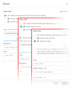 Sharing with Project Members allows you to share files with other project members who already have at least view-only permissions for the file. Simply navigate to the Files section in Docs, select the desired files, and click on the three dots at the top. Choose “Share” to access the sharing options. From there, you can send files to project members via email directly from
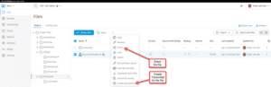


")

_hr")